ICEINSPACE

|
How to Control the Losmandy Gemini using Bluetooth
Submitted: Tuesday, 12th July 2011 by Brendan Smith
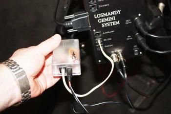
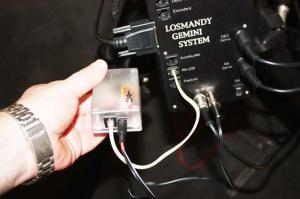
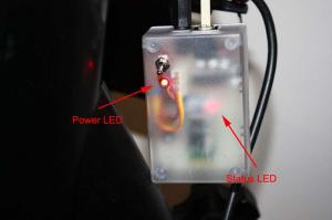
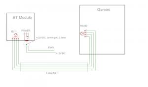
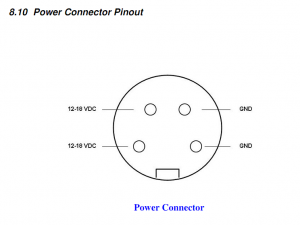
OverviewThis is document details the “how to use” cheap Bluetooth (BT) technology project to control your Losmandy Gemini (1) mount via a computer thru the Gemini RS232 port. The range I have tested this to is around 5~8m indoors (depends upon walls between you and the module) and 16m+ outdoors. HardwareThe hardware used is a home made BT RS232 module using a cheap BT transceiver from eBay, see below. Basically this transceiver input/output is routed thru a MAX232 RS232 IC to convert the signals to a useable level for Gemini. The module requires an 8-18VDC power source (readily available if you’re using a Gemini) and a 4 pin RJ11 cable (supplied). The Power connector on the module is centre positive, 2.5mm DC jack. The PCB was placed in an ABS jiffy case to reduce possible interference from carbon/metal type cases. Which is a bit of a mistake as ABS has CH bonded carbon…so yeah…Doh! OS & SoftwareThe transceiver/BT dongle needs no drivers except inbuilt MS software, XP/Vista/Win7 or any OS that has inbuilt BT control. You can read more details about the transceiver from the MDfly electronics store here. I did originally have some issues with my Laptop BT MS software (see below). There are a number of ways to overcome this however the easiest for me was to downloaded and use Toshiba BT stack software, which cured all issues, read on below for more on this. BT DongleI purchased a cheap dongle that just plugs into a spare USB port! This device will usually set itself as COM10 (in) although you can change this assignment by using the Windows BT software. If you have inbuilt BT then you do not need a dongle! Powering onPlug the Gemini BT module into a +12V DC source, switch on the device and the power led will illuminate and the transceiver status LED will start flashing. If it passes this it is ready to use, if not see “issues” below. Connection and OperationPower off the device and connect the BT RJ11 to the Gemini RS232 RJ11 using the 4 pin RJ11 cable. Connect power to the BT module then switch it on. The LEDs will illuminate as stated above.
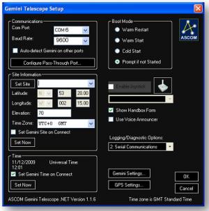
Now pair the device with your laptop BT. This is easily done as you can prompt your BT software to search for devices in range. It will/should discover the Gemini BT device and assign a COM port to it and ask for a passkey (although some BT software only asks for the passkey when you try to connect) which is “1234” (without quotes). If you use a BT dongle it will also assign a COM port for it as the incoming port and the transceiver COM port as the outgoing device. I believe this passkey can be changed with windows HyperTerminal? The device should automatically set itself as a Serial Port Protocol (SPP) mode, just check this with the BT paring. Once paired you are ready to connect to the Gemini ASCOM driver. Just start Gemini ASCOM and enter the “Configure Telescope setup” menu
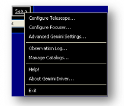
In this page you enter your BT Transceiver COM port number (found using you computer BT software or device manager) and set you Baud rate for least say 9600bps. I have tested connection speeds up to 115200bps but I only see small improvement using such a higher baud rate (like a little more responsive to key strokes). That’s said, higher baud rates are probably more prone to transmission interference. Also un-tick the “Auto Detect Gemini on other ports” as this relaxes the COM port timings allowing for greater COM delays like that thru BT
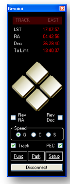
Once all entered, close this screen and go back to the Gemini ASCOM “virtual hand-paddle” screen and select “connect”. The system will connect to the transceiver, the virtual-hand paddle will display the Gemini data (after a slight delay) and the transceiver status LED will stop flashing and be fully on (not flashing).
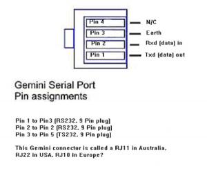
You can now control all Gemini ASCOM functions thru the connection just like an RS232 but without the wires. One last thing! I noticed if I travel out of range (with my laptop) then re-enter range the BT device disconnects then re-connects automatically. If you pressed key-strokes on the virtual hand set when outside range, once you re-enter the key strokes will be performed once re-connected. The BT transceiver has a buffer? Just be aware of this! IssuesBT Stack portsBluetooth control software uses virtual ports stacks created by MS Bluetooth virtual stack (or a 3rd party vendor such as Toshiba BT stack or Bluesoleil). I found the MS software (in my case, Win XP pro, 32bit) can have an issue in correctly writing the COM port values and sometimes you get funny port numbers like “COMo9” or “COM9c” or such like. I found this happened to me on a WinXP and also on a different Win7 machine. Some other users have reported this issue but most users will never see this. Another WinXP home netbook I use for astro work did not have this issue. I just mention this as I faced this hair pulling exercise. HKEY_Local_Machine/Hardware/Devicemap/SERIALCOMM Now edit the value for the port by deleting the COM port value for your outgoing port, mine was “COM9”, then re-entering “COM9” (without quotes) (or what ever the BT COM ports are). Do the same for COM10 port (or what ever the BT COM ports are). \Device\Bthmodem0 REG_SZ COM9….edit this COM9 and re-enter COM9. Ok you may now point out that your are just entering the same data that is already there, but this is only partly correct. The MS stack assignment has written values you cannot see unless you look at the binary data values in reg-edit. If you have “funny” COM port numbers then there are “hidden null” values there you cannot see. Deleting this COM port data and re-entering them re-writes the values. As mentioned an easier fix for all this is to use a 3rd party BT software, see above. RJ11 cables, 4 pin (4P4C)I’ve had some trouble correctly crimping RJ11 4P4C cables as I had the wrong crimper. I do test the cables but they are all a little dodgy. I have seen this manifest as “it won’t connect”! You see the transceiver status LED go “on” for a few seconds (its communicating with the transceiver) then it starts flashing again (the RS232 COMs failed). I do test the cables but watch out for this. If you have to replace the cable do note the interconnection method I used for the cable. New crimper already ordered! Circuit protectionThe module has a reverse polarity protection schottky diode. If you inadvertently apply power in reverse polarity the module will not work but the circuit will remain unaffected/un-damaged. The module has a TE5, 125mA fuse. If this blows (it shouldn’t) then the power LED and status LED will not power on. There could be many reasons why a fuse has “blown” and I doubt any RS232 issue would cause this, more likely a circuit fault which needs to be rectified The circuit uses a small +5V regulator and I draw is around 50mA max. The PCB has been conformal spray coated for moisture protection. AttachmentsAttached are resources you may need to construct this project.
Module Schematic Interconnection
Article by Brendan Smith (wasyoungonce), contibutions by RickS. Discuss this article on the IceInSpace Forum.
 |
|
||||||||||||||||||||||||||||||||||||||||||||||||||||||||||||||||||||||||||||||||||||||||||