ICEINSPACE

|
Spectroscopes: Part 2 New 200mm Littrow design
Submitted: Wednesday, 16th July 2008 by Ken Harrison
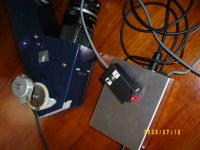
This article is part 2 - an update on Classical Spectroscope article from almost 2 years ago. The instrument has generally performed well over the last year. The beam-splitter as designed was not a success, due to alignment problems and was removed. Also, the original design of the stepper drive for the grating proved to be inadequate and was replaced by a tangent arm control. Recently a Meade Off-Axis Guider body has been modified to house a beam-splitter and this has been found to be a good solution.
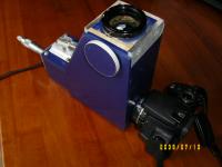
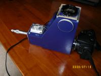
It allows the spectroscope to be aligned with the star under observation and guided, using a Webcam. Finally, using a stepper motor controller from Surplus Shed, I have managed to get single step by step control of the grating! A small hand paddle was built to give pulse and direction control. (See photo) This makes indexing the grating for the field of view of the camera much easier.
The current configuration uses the 600 lpm grating and a 50mm Zuiko camera lens. This allows me to get a full spectra on the frame of the Canon 350D. The shorter focal length camera lens reduces the normal 20 micron slit width to about 8micron on the CCD chip, (50/135 x 20) which also improves the resolution to better than 1 A / pixel. I have found however that although the Classic performs reasonably well, it still has some problems. The accuracy of my workmanship in the positioning of the collimating lens, slit and grating let me down. I get distortions in the spectra, the mounting and change-over of the various cameras is not as robust (i.e. getting focus and alignment) as I hoped and the physical size causes balancing problems with the smaller telescopes. With these issues in mind I took another look at the Littrow design, which is a more compact optical arrangement. New 200mm LITTROW DesignThe first serious spectroscope I built was based on Maurice Gavin’s WPO design. This is a very elegant, compact design based around a telephoto lens.
Unfortunately, in spite of major “surgery” and a couple of re-builds I was never able to make it a success. The limited back focus available to position the prism and get the CCD into position beat me. However, the basic Littrow design has a lot going for it. The use of a single lens makes it much lighter than the Classical and being more compact, it’s easier to mount (and balance) on the telescope. The only down-side is that the “camera” lens can’t be changed to give narrow images of the slit (which can improve resolution). The commercial LHIRES III spectroscope from Shelyak Instruments is a Littrow design and is widely used for semi-scientific work by amateurs. Buil’s page has the necessary calculations for the lens/ grating size etc. With this in mind, a new Littrow spectroscope was built around a 52mm f 4 lens (recycled from a photographic Blink Microscope I built in the 80’s), using the Surplus Shed adjustable slit and a new 30mm x 30mm grating support. The basic “box” is once again 60mm x 60mm x 6mm Custom wood, with 16mm sheet used for the various supports. The overall dimensions are 200mm x 200mm x 80mm, and weighs in at only 1220gms (this is 500gms less than the original!) The incoming beam is directed to the collimating lens via a prism (old binocular prism) positioned just above the optical centerline of the lens. The axis of the grating is slightly tilted to cause the return beam to follow the optical axis back to the camera.
I’ve actually made a diaphragm aperture 35mm x 35mm at the collimating lens. This is all that is needed to fully illuminate the 30mm x 30mm grating. This stop effectively turns the instrument into an f6 system. Ideal for both the LX200 (with the x0.63 compressor) and the Genesis/ ED80. Using a 300 lpm grating, this arrangement gives a very bright spectrum which easily fits the field of all my CCD’s. The theoretical resolution is about 2.5 A, more than sufficient to identify the stellar absorption lines for the various classifications. It’s any easy instrument to use and fits well with the smaller telescopes like the Genesis and the ED80. ConstructionA lot more attention to detail this time round. I kept the T2 mounting idea; works well with no major problems. To ensure minimum distortions etc the optical axis from the camera must be kept square to the collimator lens and the grating, my target was to be within 0.1mm. The ability to easily focus the various cameras (and be able to use various power eyepieces for visual work) was paramount. Positioning the grating required improvement of the shaft support and a method of angular adjustment to align the slit as well as a smooth rotation of the grating with an indicator of position. The inclusion of a reference light source (Neon) was necessary to improve the final calibration of the spectra. Key points:
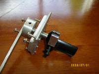
As I’m limited to the usual collection of hand tools the construction had to be straight forward (I must admit the pedestal drill press and the Mitre saw table helped!) Using a digital vernier I worked on each piece of the assembly to get the accurate positioning of the holes for the mounting ring, slit assembly, collimating lens, grating housing and the camera/ focuser. Measure three times and before cutting, double check again! An adjustable wood hole drill gave the flexibility of drilling the correct size holes for the various elements (trial holes being cut in scrap until the final dimensions were correct). Some points of note: a. Laser CollimatorA small red laser pointer was modified by removing the nose piece and adding a mask made from a “precision” pin hole in aluminium foil. This was necessary as the original “optical axis” of the laser beam was well off-centre and spread to an unacceptably large image.
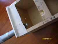
The pointer was mounted, using 6 small screws at 120 degrees, into a surplus 1 ¼” x 1” extension tube. With trial and error the pointer was accurately positioned in the center of the tube and aligned with the axis such that there was no movement of the spot when projected on a wall 4 metres away and the tube rotated. Much cheaper (and more accurate!) than the commercial model. b. Grating housing and adjustmentI used an 8mm piece of bright mild steel bar as the shaft and purchased an 8mm precision bearing ($5) which was a press fit in the machined housing. The grating support was milled from a 25mm diameter piece of aluminium bar with the land for the grating off-set by 6mm to bring the front face of the grating onto the centerline. Later I glued ( araldite) a 3mm x 6mm aluminium tab to the back of the holder to allow the use of a micrometer head ( 1” micrometer, Ex-Ebay, $4) to adjust the position of the grating.
To minimize errors in adjustment I also glued a 6mm ball bearing on the nose of the micrometer shaft to act as a bearing point on the tab. The grating has to be tilted about 4 degrees in my design to get the primary beam from the slit/ prism to return along the optical axis back through the collimator to the camera. This is achieved using a push/pull screw arrangement on the bearing housing. Final adjustments being done using the laser collimator. c. Camera/ focuserAfter much thought and trials with PVC pipe fittings etc, I “bit the bullet” and purchased a Baader T2-T2 rotational adaptor (#BA2456320) and a T2 to1¼” micro-helical (4mm travel) focuser (#BA2458125).
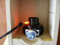
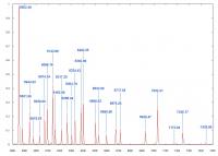
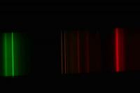
Not cheap but very, very effective, (38 € each) these adaptors allow the spectroscope to be focused for the Canon 350D, which needs 55mm back focus (worst case scenario) and then by inserting the micro-focus unit and T2 spacers, the other camera/ eyepieces can be mounted and brought to focus independently. The T2 rotational element allows the camera to be orientated to the spectrum without changing the focal position. Baader adapters. d. Reference light sourceI use both a Neon indicator bulb and an Osram Fluoro energy saving bulb (Duluxstar) to provide reference spectral lines, but have not previously incorporated them into the spectroscope. To achieve maximum accuracy the reference source must be imaged using exactly the same grating position and camera, so obviously it is far more convenient to have the reference light inside the spectroscope and take an image before and after a spectral exposure. The Neon is the most “recognized” standard, and all the emission lines are fully documented (see graph below). The small neon bulb is located in front of the slit and a 9mm prism is positioned to throw the light on the bottom section of the slit. When the bulb is switched on, it provides a “reference” spectra in the camera.
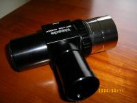
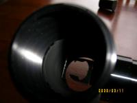
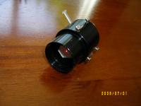
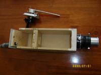
The following photographs show the various components during the “dry fit out” testing. The back focus requirements of the Canon camera automatically determined the distance to the slit.
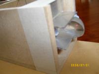
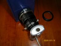
To provide access to the slit and reference light, the side panel is removable; the grating and collimating lens can be accessed through the top panel of the collimator section.
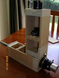
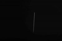
After sub-assembly and painting, the laser collimator was once again used to confirm everything was correctly aligned, the collimating lens block was then glued in position. The slit was positioned and the prism angle double checked. The grating holder was then inserted and aligned to the center of the camera adaptor with the laser. Using a 10mm eyepiece positioned 55mm behind the T2 camera adaptor, the slit was adjusted to perfect focus, then the slit mounting block glued in position. The final position was double checked by setting up the Canon and taking some exposures to confirm alignment and focus. (See photos).
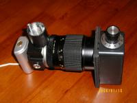
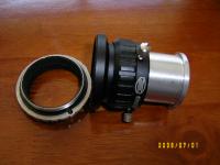
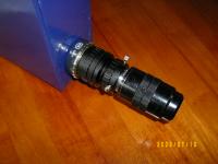
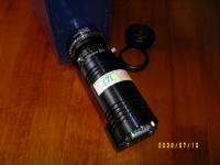
These photos show the final spectroscope, almost ready for use.
The slit was aligned to the grating by eye and locked into position. The “zero order” position was established on the micrometer and verified by moving the grating through its full travel back to the zero position. The attachment of the various camera and eyepieces is shown in the photos.
SummaryIt is possible for the average amateur astronomer to build a “research grade” Littrow spectroscope for less than $400. The compact design allows easy use with a variety of f6 focal ratio telescopes and the resolution achieved is close to the theory. The commercial equivalent currently costs over $5,000, so home construction can save a LOT of money, besides giving the satisfaction of constructing an accessory which can be used for solar, planetary and stellar research. Further ReadingI found these books to be useful, and helped me understand the issues (and solutions!) involved in getting started in astronomical spectroscopy.
The following books are also available on the web for download at www.archive.org . They give a wonderful insight into the early years of spectroscopic development.
 |
|
||||||||||||||||||||||||||||||||||||||||||||||||||||||||||||||||||||||||||||||||||||||||||||||||||||||||||||||||||||