ICEINSPACE

|
Basic Setup Procedure for a German Equatorial Mount (GEM) Telescope
Submitted: Wednesday, 16th July 2008 by Trevor Hand
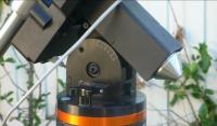
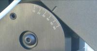
IntroductionThis document is designed to give a general overview of the procedures for setting up an equatorial telescope for visual viewing. A number of terms will be introduced throughout the document without any prior definition (eg. latitude, right ascension, declination, celestial pole). If a more detailed explanation is required, this can often be found in the instruction manual that came with the scope or from other sources such as books, magazines or the Internet. It is assumed your mount is of the same basic German Equatorial Mount (GEM) design and so, although they may look different, they are all fundamentally the same. The directions are “south centric” and so people living in the northern hemisphere will need to convert any references that are hemisphere specific. Don’t be put off by the seemingly complex detail of my instructions, by being verbose I hope to answer or clarify any queries you may have. After performing the procedures a few times, many of the tasks can be completed very quickly; it will usually take between 5 and 10 minutes to set up the complete mount, even in a different location to your normal one. When completed, the telescope alignment should be good enough to allow the user to locate and follow most objects in the sky. The procedure does not cover drift alignment or other more detailed techniques to get sufficient accuracy to allow long exposure photography as details for these techniques can be found elsewhere. Whilst the whole procedure consists of many steps, a number of these only need to be performed once (eg. setting latitude) or are always set to the same position each time (eg. balancing the tube) making subsequent setting up much quicker. The instructions are targeted at the beginner level observer as more experienced viewers will already have their own set up routines, many of the steps will be identical to those described in this document. The first time an equatorial mount is taken out of its box the user is confronted with a myriad of adjustments and instructions. Unfortunately, most of these will need to be performed with at least some degree of accuracy, eg. you cannot use an EQ mount properly if it is not at least facing roughly south (or north) or locate objects in the sky if the finder is pointing in a very different direction to the main tube. The first experience most of us have of a telescope is an altitude azimuth (Alt-Az) mount, one that turns left to right and up and down (this not only includes camera tripods and the conventional mounts favoured by “department store” telescopes, but also the ubiquitous Dob and fork designs). The first thing you experience with an EQ is that the movements are somewhat “un-natural”. As you move the scope around to point to an object you begin to get closer and then the scope will get further away as the same axis is moved further. After some practice you will learn to approach with one direction only part of the way and then swap to the other axis, alternating until you eventually home in on your target. In the case of the EQ mount, it moves up and down in the declination axis just like the familiar Alt-Az, but the other direction, Right Ascension (RA), moves around a fixed point in the sky, the south celestial pole in our case. It is this movement that makes the EQ mount so confusing. You will also find that as you move to different locations in the sky, the eyepiece will end up in some very awkward positions. In the case of SCT and refractor designs, the eyepiece will often end up very low to the ground when observing near the zenith, making it necessary to sit for some observations. A diagonal will often help in this case to make the viewing easier. With Newtonian type scopes, the eyepiece seldom ends up being too low, instead these scopes suffer from the opposite problem. At times you will need to be 8 feet tall and be able to bend over the telescope without touching the tube at all in order to view. Changing the direction of the eyepiece with a diagonal is not usually an option with a Newtonian either as they will not have sufficient “in focus” as the diagonal will make the light path much longer and you will run out of inward movement before it comes to focus. There are various accessories that can be used to allow diagonals and binocular viewers to be used, but these will only work with certain manufacturers accessories. The tube rings can be loosened to allow the tube to be rotated, bringing the eyepiece into a more suitable viewing location, however you will need to ensure the tube does not slide out of the rings and rotating the tube may also alter the balance of the tube. Often the best way to overcome such problems is to utilise a ladder or to build some sort of viewing platform to allow access to the eyepiece when it is pointing very high. Setting the basic parts of the mountBefore attempting to set up any sort of rough alignment, there is a simple task that will need to be performed or determined once only. It will only need to be performed again if you change the location of the scope by a significant amount. Setting the scope up in the front or backyard won’t require resetting, however moving from Melbourne to Sydney will. On the side of the mount there will be a circular scale that needs to be set to your latitude, in our case setting it roughly to the correct position will suffice, for long exposure photographic use this will need to be set precisely using other techniques such as drift alignment. Table 1 lists the latitude and other detail of some major cities in Australia and New Zealand.
Table 1. Geographical information for various locations. Don't forget to adjust for Daylight Savings Time in your location. Simply adjust the latitude screw until the pointer on the scale is set to your local value. There is normally a screw near the latitude scale that will tilt the mounting head upwards by pushing against the base. Loosening the screw will allow the mount to drop in declination. Larger mounts may also have a second screw to lock it into position. If you find it difficult to adjust the tilt, check that you have loosened the locking screws, unfortunately not all manuals will tell you where they are!
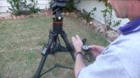
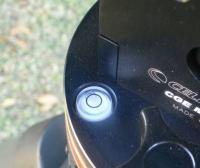
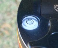
The other value you will need to determine is the magnetic deviation at your location, this is the amount a compass will point “away” from the real South Pole. Most locations in Australia and New Zealand have a deviation to the east. To compensate for this deviation, face to the south and align your compass to the South Magnetic Pole. Using the table above, find the deviation value and take note of an object that has that bearing from where you are. If the deviation is east, the bearing will be to your left when facing south, eg. in Melbourne I face south and align the compass to the south and then take note of something about 11 degrees to the left of due south. This is the point I would face the centreline of the tripod mount. If the tripod is already placed on the ground you will need to ensure the compass is not affected by any iron in the tripod itself, this can be determined by walking up to the tripod and seeing if the compass needle points to the scope as you approach it. If it is affected, you will need to do your alignment away from it. With some practice you will get a feel for the amount of deviation to apply and will be able to dispense with the compass when setting up in your favourite locations. In my case, when looking at my southern boundary fence, I am looking exactly due south, I simply need to face my fence and turn the tripod to point directly at it. Putting the tripod in placeNow that the constants in your set up have been determined we can begin by placing the scope in a suitable position. In the suburbs this may be determined by the location of other houses, trees, lights etc. and will usually be some sort of a compromise between them all. On some tripods one of the legs will be marked with an “N” whilst on others there will be no such markings. If you have a “north leg” face this leg in the direction you determined earlier as being “true south” (you will find that most astronomical equipment, books and magazine articles are north centric so you will usually need to do a conversion in your head). If you don’t have a north leg, you will need to determine which leg has the counterweight bar aligned with it when the scope is in a neutral, or home, position. This is your “south leg”. On some tripods the head assembly will only locate in one position and so this leg is fixed. Other tripods allow the head to be positioned in several other locations, in this case the head should always be attached with the counterweight bar aligned with one of the legs, and this leg should face south. If the counterweight is not aligned with a leg, it may become unstable and topple over. The next task is to ensure the tripod is at least approximately level, most tripods will have a built in level to assist in this task. You may like to check the accuracy of this by setting the tripod on a firm base that can be checked with a more conventional spirit level. This could be a floor, concrete path or deck if you have an area that is level already or place it on a large board that can be made level by packing. Place the tripod on this level location with all legs completely closed up and check that the tripod bubble is centred properly. If it is not, you could place a mark where the bubble is located to give you a more accurate level indication or you may prefer to use a conventional ‘bullseye” spirit level that can be purchased from most hardware stores.
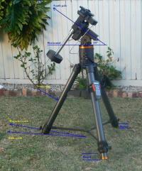
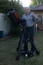
Adjust the legs of the tripod by extending them until the bubble indicates the tripod is level. This is easiest done before the scope is placed onto the mount, particularly if it is quite heavy. If you stand to the side of your set up so far, you will see that the dovetail mounting base is pointing at an angle to horizontal (by your latitude angle), the centreline through the tripod will be pointing directly south and the counterweight bar will be hanging directly under it. The top of the dovetail mount will be pointing, at least approximately, at the South Celestial Pole. All the stars will rotate about this point and so by moving the scope in one axis only it will compensate for the rotation of the earth and an object will remain in the eyepiece. This position is normally called the “home position” and is the location where the least amount of strain is on the various drive gears and motors. If you store your scope assembled, it should be kept in this position. Note that many heavier scopes are not recommended to be stored assembled, check your manual to see if they recommend storing your scope in bits.
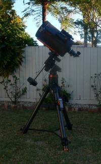
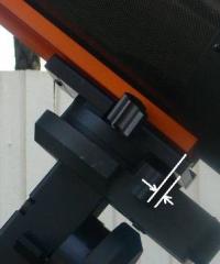
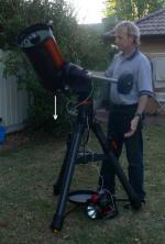
CounterweightsThe next thing is to attach the counterweights to the counterweight bar that hangs down from the mount. Ensure the safety screw is removed from the end of the bar before attempting to slide the weights onto the bar. Initially, the weights should be placed somewhere near the bottom of the bar. Tighten the locking screw on the weights and replace the safety screw to prevent the weights sliding off and onto your toe when you are balancing the set up. Never remove the counterweights from the bar when the scope is attached to the mount and the scope should never be placed onto the mount before the counterweights have been attached. After a few trials you will quickly determine approximately where to place the weights and can mark the position if you always use the same set up when viewing with a Texta line. Attaching the OTAThe final stage of assembly is to place the Optical Tube Assembly (OTA) onto the mount. In most cases this will be via some sort of dovetail rail that will slide down or into a matching fitting on the mount head. A screw will usually press against the dovetail bar to hold the tube in place and stop it sliding out and onto the ground. In some cases the dovetail may also have a locking screw or bar to prevent it from sliding through the mount and onto the ground. When the tube has been balanced, you can move this locking bar against the head to make it easier to balance next time. Because the majority of the weight in the tube will be at the bottom if it is a reflector, or towards the front for a refractor, you will need to place the tube on the mount at somewhere near the balance point of the tube. If there are tube rings that hold the OTA to the dovetail, these can be adjusted before mounting on the tripod to place the centre of gravity of the tube somewhere near the centre of the dovetail rail. When the OTA is placed onto the mount, this centre of gravity point will be near the centre of the fixture that holds the dovetail in place. With an SCT scope the dovetail will be attached to the bottom of the tube. In this case, most of the front of the tube will overhang the mount as the vast majority of the weight is at the rear. The more accessories you place on the scope, the more you will need to adjust where it is placed initially on the mount. If you use a camera on the tube, you will need to place the tube in a different position compared to when the camera is not attached.
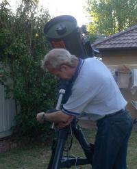
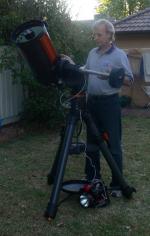
Balancing the tubeWhen the tube has been placed onto the mount it will need to be balanced. This will ensure if the locking clamps are released the scope will not suddenly tip to one side, possibly causing damage. It will also reduce any strain on the gears used to move the scope. Before balancing the scope, place the eyepiece into the focuser that you will be using for most of your observations. Also attach any other accessories to the scope at this time such as guide scope, camera, laser, diagonal, field flattener, visual correcting accessories, electric focus etc. Also remove the covers from the finder and tube. Once the tube has all the components that are going to be used mounted in their normal positions we are ready to balance the scope. If you use a number of eyepieces that vary significantly in weight, you may need to use some sort of extra counterweight scheme, perhaps adding an extra weight to the tube when a particularly heavy item is placed onto the tube to help maintain a reasonable balance. If you add significant weight to the tube assembly, you should also add an appropriate weight to the counterweight bar or move the counterweight further down the bar to compensate.
The first adjustment is normally performed on the RA axis; this is the one that will tip the tube from one side of the mount to the other. Note: when making any adjustments to the balance, never completely let go of the tube assembly. Locate the RA locking clamps and carefully release them. Gently tip the tube over to one side and carefully release it, just enough to determine if it is “heavy” or “light”. If the tube tips towards the ground, the tube is heavy and the counterweight will need to be moved further along toward the end of the bar. If the tube comes up to meet you, the weight will need to be moved closer to the tube. Move the tube back into the upright position with the counterweight bar pointing down and lock it back into position. Carefully slide the weight along the bar in the appropriate direction, after a while you will get a feel for how much to move it. Lock the weight in position again and release the RA axis. Gently tip the scope over to one side again to determine if the scope is heavy or light. Continue this process until you are happy with the balance.
On some scopes you will notice that it may appear to be balanced on one side and unbalanced on the other side. For our purposes, we would just compromise to find a balance point that is reasonable on both sides. I have found with a Newtonian scope that the best balance is possible if the centre line through the counterweight bar and the axis of the focuser are in line, ie. when the counterweight bar is pointing down, the eyepiece is pointing directly up. If they are significantly different, you will find the tube will balance on one side, but be quite out of balance on the other. This will be exaggerated when using heavy eyepieces (such as most “wide angle” or 2 inch eyepieces). You will also find that in some positions the eyepiece will point at the ground. Having the axis of the focuser and bar aligned will give a “worst case scenario” of having the eyepiece point horizontally. Even after all of this balancing you will still find it impossible to get the same balance on one side as the other, this is due to the fact that the weight of the accessories such as the finder, laser, TelRad etc are not balanced on the tube. As the tube turns about the centre of the mount, the distribution of the weight changes as the accessories come closer to or further from the centre of the mount axis. For our purposes, we will be content with a compromise. The tube is now balanced in one direction.
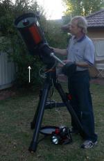
Next we need to balance the tube in the other direction, declination. Tip the scope to one side as in the previous step but this time lock it into a horizontal position. Now carefully release the locking screw for the declination axis. This will cause the tube to dip and either point toward the ground or up to the sky. Gently release the tube and note which direction the tube moves. If the front of the tube points to the ground, the front is too heavy and the dovetail will need to be slid along the mount toward the back. If the front points upward, the rear is too heavy and the dovetail will need to be slid toward the front.
Level the tube again, lock it into position and return it to the home position. Gently release the dovetail locking screw and carefully slide the tube in the required direction. Be very careful to always hold the tube when this screw is released, otherwise it may allow the whole tube to slide out and drop onto the ground causing very serious damage. Tighten the locking screw again and tip the tube over. Release the declination-locking clamp and recheck the balance again. Repeat this process until the tube stays in any position you place it without tipping either up or down. You will quickly learn just where to place the dovetail bar on the mount in order to balance the tube
If you make any large changes to the accessories used you may need to recheck the balance again. Attaching an SLR onto the focuser will dramatically alter the balance of the system, making is necessary to rebalance the whole assembly again. In this case, you may like to make a set of small counterweights that can be added to the scope and counterweight bar to offset the change in weight, allowing you to maintain a good balance without needing to rebalance the whole thing. The scope is now ready to do some observing, unless you have a goto!
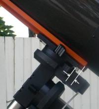
Aligning the GoToIf your scope has a GoTo system, you will then need to align the computer system in the telescope. The computer needs to know various parameters about its location, date, time etc and also needs to be pointed to a number of stars so it can model the sky inside it’s tiny electronic brain. There are normally several options to select when aligning the scope. If it is permanently mounted, you can choose to use the last alignment. In our case though, it is assumed the scope has been moved and so using the last alignment will not be very accurate so we will need to select the appropriate number of alignment stars before we can start to seriously use the scope for the night. If you are not going to be using the GoTo facility and instead will be star hopping, you could choose the last alignment option. You can then manually move the scope from one location to another by using the control pad. A laser or TelRad will prove useful for locating objects. Before alignment can commence, the scope will need to be placed in some sort of reference position, usually also called the home position. Some tripods will have alignment marks on both axes that must be set correctly, perhaps two arrows that must face each other on each axis. Other systems may have some sort of internal switches to indicate when the scope has reached the home position. From this position the motors should have an equal amount of movement in both directions, if this home position is not set correctly, you may find that the scope cannot travel to the horizon in one direction or cannot slew fully to the north or south. After setting the home position, you will usually be asked for information about the viewing site. This will consist of the following, but not necessarily in the same order.
When entering the date, take note to enter day and month in the right order, many scopes expect the month first or MM/DD/YY, ie. 08/04/07 is 4th August. If you get this wrong, your alignments won’t work very well. Check the table earlier in this document for some of the values required by the computer. Alternatively, many GoTo scopes can utilise a GPS unit that will provide the computer with all of this information. The first time you use the scope you should also ensure that the scope is set to tracking in the south, if it is tracking in the north, the tube will turn in the wrong direction. We will assume you will be using just two alignment stars in our case; selection of a different number of stars will usually follow the same procedure. You will be presented with your first star that you will need to be able to locate. If you cannot recognise the star or it is covered by a tree or house, you will need to select another one. The scope will then slew to where it thinks the star is located. In some cases this may be out by several degrees, or it may be quite close. Using the manual jogging buttons on the controller, slew the scope around until the star in question is in the centre of the finder cross hairs, see Aligning the finder (below) if the centre of the finder does not point to the same location as the centre of the eyepiece. To aid in aligning with the star various accessories can be utilised. A green laser pointer can be mounted on the scope and aligned with the eyepiece. When these are turned on, a visible beam is projected into the sky for several hundred metres (reminiscent of a science fiction movie) making it very simple to determine where the scope is pointing. Note that in some states such instruments need to be licensed and cannot be operated by people under 18 years of age. In some dark sites the use of these are restricted or banned as the light may affect people nearby who are imaging. If the ambient temperature drops much below about 15 degrees Celsius, the laser diode will become very dim and may not even be visible. Another useful tool is a “zero power” type of finder. One of the most popular is the Telrad, but they all work in a similar manner. A visible target is projected onto a clear plastic window. When the sky is viewed through this window, the target is superimposed over the sky, which remains visible through the clear plastic. When the target is centred over the alignment star, it should be close to the centre of the finder. When the star is aligned in the finder, you will normally be asked to press a button and then to align the star in the eyepiece. When this button is pressed, the scope will usually switch to a slower slew rate. The rate required to slew an object into the finder is much faster than to centre in the eyepiece. The most accurate way to centre in the eyepiece is to use a special eyepiece with an illuminated reticule (cross hairs), I use one with a double cross hair which gives a central boxed area to centre inside. Many companies manufacture these and they will normally have a focal length around 10mm to give a good degree of magnification without becoming excessive. Gently jog the star into the centre of the reticule or into what you judge to be the centre of the field of view. To reduce any affects caused by backlash in the gears, many manufacturers recommend that the final approach to the star be done with movement from a certain direction on the control pad (you can refer to the manual of your scope to determine which ones). When the alignment of the first star is complete, you will be asked to align a second star. This should be several degrees away from the first one. The further away the alignment stars are, the more accurately the computer will be able to model the positions of objects in the sky. When the second star is selected, the scope will slew to it. Normally you should find that this alignment will be much closer than the first one, often it will already be very close to the centre of the finder and sometimes may even be visible in the eyepiece. Follow the same procedures as before, aligning the star in the finder and then the eyepiece. In some cases, your alignment will now be complete. The computer inside the controller uses the entered parameters and the data from the alignment stars to create a model of where all the objects are located. The controller also contains functions that can calculate the location of objects that are constantly moving, eg. planets, and can move to this location when requested. This allows you to go to an object such as the Moon early in an observing session, when it is located at a particular RA and Dec and to return to the Moon again several hours later in the same session when the Moon is located at a different RA and Dec. The fixed objects, stars, galaxies, nebulae etc. are in a fixed position and so these are simply stored in a table inside the controller. When a position is requested, the co-ordinates are extracted from this table and passed to a function that calculates how far to move the axes to point to that location. During the night, this “fixed” grid is slowly rotated as the Earth turns, allowing the scope to point to the same target several hours later. If your scope requires more alignment stars you will be presented with the next selection. Some systems may require selection of two stars in one hemisphere and only one in the other one. I have found that on some occasions I have been unable to identify more than one star in the direction requiring two. By selecting the same star again, I was able to get reasonable slewing accuracy and so if you find yourself in this situation, it may be worthwhile trying this option. Alternatively, some systems allow you to press a button (Menu on mine) that will switch to the selection of two stars in the other hemisphere and one in the first. Other more advanced systems also allow extra stars to be added to the computer model. As more stars are added the pointing accuracy will improve. The extra stars should also be placed around the sky and not located near stars already used. If you find that during the night the slewing accuracy is getting worse, you may need to replace some of the alignment stars with others. The method of performing these changes is very dependent on the manufacturer and so you will need to refer to your scope manual. Several people have noticed that if you take a very long time to align each star, the accuracy of your alignments seems to be severely compromised. This may occur if you are unable to identify a suitable alignment star and need to refer to a star chart or planisphere. It appears that during the alignment process, the computer does not allow for the passage of time while aligning each star and as a result the previous stars drift from their expected positions. I have also noticed a similar phenomenon myself on a couple of occasions. In order to minimise this effect, I recommend performing the alignments quickly and accurately. If you need to stop for an extended period during the alignments, it may be worthwhile starting again. I have also found problems if my first alignment star is very close to the meridian, about to switch from the east to the west. On one occasion the scope “went nuts” and continued moving until I aborted the goto! I there for always select stars that are a few degrees before the meridian. For greater setup accuracy, you can slew to the first alignment star and then adjust the mount in altitude and azimuth to align this star and use the keypad to align subsequent stars, however, for normal visual use the computer model should be able to cope with any initial alignment inaccuracies. These could be caused by the scope not pointing accurately to the south, not being level, declination not set accurately to your latitude, inaccurate time entry etc. Aligning the finderBefore the telescope can be used effectively, the finder and telescope should be aligned with each other. Once set, the alignment will only need to be checked occasionally or if the finder has been removed or adjusted. The whole procedure should only take a couple of minutes and is best performed during the daytime. Having a reticule eyepiece in the telescope for aligning the finder though will not improve the accuracy greatly. If the scope is automatically driven you will need to ensure the tracking is turned off, otherwise the scope will continue to move while you are trying to centre your target. You will need to refer to you user manual to determine how to turn this off. Don’t forget to turn it back on when you are finished! Set the scope up somewhere that has a clear view of an object 1km or so away to minimise the effects of parallax. Insert an eyepiece of medium power; around 10 to 15mm should be sufficient. Adjust the scope until an easily recognisable object; say a tree, power pole, window etc. is clearly visible in the eyepiece of the scope. Slowly slew the scope around until it is in the centre of the view. Looking through the finder, adjust the alignment screws until the same object is centred on the cross hairs. Initially, none of the object may be visible in the finder at all. By doing this alignment during the day it is much easier to determine which direction you need to move the finder to centre your target. Once the object is centred, your scope and finder are aligned with each other. If you move the scope around and centre something in the finder, it should be clearly visible somewhere in the field of the telescope. If you are using a laser finder you can use a similar procedure, but in this case it will be easier to do it during the night. Centre a star in the eyepiece and turn the laser on. Adjust the laser mounting bracket until the laser falls directly onto your target star. The laser is now aligned. A Telrad or other zero power finders can be aligned using a similar procedure, also at night. Centre a star in the eyepiece and turn the Telrad on. Adjust the alignment screws until the projected target is centred over the target star. Your zero power finder is now aligned. Resources
Article by Trevor Hand (OneOfOne). Discuss this article on the IceInSpace Forum.
 |
|
|||||||||||||||||||||||||||||||||||||||||||||||||||||||||||||||||||||||||||||||||||||||||||||||||||||||||||||||||||||||||||||||||||||||||||||||||||||||||||