ICEINSPACE

|
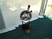
Building a Small Truss Tube Telescope
Submitted: Thursday, 2nd August 2007 by Peter Pocock
IntroductionAfter I completed my 200mm (8 inch) Dobsonian f8 telescope I wanted to build something more portable, in order to have a telescope with me when I went travelling any where in this great county of ours. Now I know that when we deal with a telescope, size does matter! However this was not a real proposition for a lightweight telescope, which was supposed to fit happily in the back of my vehicle along with all the other gear we lug about with us when we leave home for camping/holiday destinations.
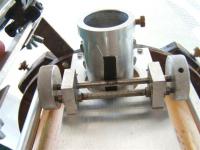
One day while reading an Astronomy magazine (I am afraid I have forgotten which) I came a cross an article from a contributor who visited Australia with the main objective of star watching at Uluru (Ayers Rock). The gent in question was from the USA and he had to be able to transport his telescope as luggage on a commercial flight, and as a result the “scope’ had to be light and pack down into a small package. Now he had my attention! His approach was for a mirror box and a simple arm for the secondary mirror and eye piece. It looked like a great idea. I have since found numerous examples of this on the internet, what a great resource that is. Any way, while surfing the ‘net I came across a link to building “Open Truss Tube Reflecting Telescopes”. Now I became very interested in this concept, and, as I am sure many of you will feel the same, I started to dream about the big end of town, momentarily losing sight of the “small” factor! Sooner or later reality took hold again and I thought that the truss tube idea could be applied to the primary and secondary mirrors I already had in my possession, namely a 150mm (6 inch) primary and a matched secondary mirror. I eventually discovered David Kriege’s book about how to build the open truss type telescope. This book is a beauty and full of great ideas, for any aspiring telescope builder. While on the subject of books another very good resource is, “How to Make a Telescope” by Jean Texereau, this has al the maths etc from whoa to go. A real diamond. With the aid if these “ideas books” I began the planning and drawing part of the venture. ParametersProbably the first objective was to build as much as could without resorting to buying “off the shelf”. This telescope’s main parameters were set for me by the size of the primary mirror, every thing else was to revolve and resolve itself around that. I already had a small selection of 1.25 inch lenses, so there was the focuser size, not that a 2 inch lens facility would be appropriate for this telescope. Plywood and MDF board would be used where I could, only because I like the look of plywood, and aluminium for lightness and strength for the tubes. The mirror cell was from MDF, you cannot see it any way, and in the base of the mirror cell are large diameter holes for air circulation. The secondary cage was to have plywood top and bottom rings held to together with aluminium tubes. The spider for the secondary mirror was to be a four van type with an adjustable configuration for collimating the secondary mirror made from aluminium round bar. Finally, the whole unit had to take up as little space as possible when in travel mode. Building Ideas and ConstructionI knew from previous experience that my parameters could all be met albeit in some different ways and with some careful thought, improved upon. One example of this was the focuser. I wanted a Crayford type, similar to the version I made for my first telescope.
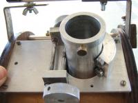
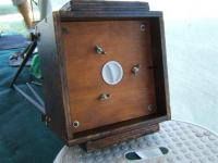
My first effort was remarkably smooth and incorporated plain bronze bearings. I felt that by using small ball bearings where possible I could do even better. Thank goodness for model aeroplane motors, they are a great source of small precision components at a small price. Four small ball bearings were used for the lens tube to move in and out on. It turned out to be so smooth I started to entertain the idea of a motorised focus system, this I have not done as yet but I have the planning done ready for when I do build that refinement. You may think that holding a mirror in this way is a bit rough and ready, I can assure you the only way to get the mirror off the cell is to cut through the Silastic with a small saw blade, it is very tenacious stuff. By the way, the mirror was the very last thing to be mounted in the whole unit, and only after I was satisfied that no more work was to be done to the telescope. Just playing safe! The truss tubes were to be 12mm diameter aluminium tube, covered in black heat shrink plastic, it worked a treat. In one end of those tubes, for about 30 mm, I glued close fitting wooden dowels so the ends of the tube would not crush when clamping the secondary cage to the tubes. I began building the primary mirror box and cell first. The box sides and top were made from plywood and glued and screwed together. The mirror cell was mounted on a square base which in turn was a close fit in the bottom of the box and attached by round head screws with washers under the heads. This was done in case I had to remove the mirror for any reason. The mirror cell has three captive bolts embedded into it, equally spaced around the inside edge of the mirror cell. These in turn had a small open wound spring placed onto them and then the cell was offered up to the mirror box base and is attached to that by washers and wing nuts. Collimation is very easy with this approach. The base of the box was is let up into the sides so that nothing protruded from the bottom of the mirror box. Alignment is assured by gluing four rectangular gussets on the inside corners of the box, and of sufficient cross section to take the mirror base screws, allowing the mirror box base to accurately relocate any time it is removed. When I had occasion to remove the mirror box base and mirror cell, all went back together again simply and accurately. Just to be sure I had a single line made on both pieces so there is no doubt about where the parts line up.
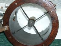
Next was the secondary cage, which houses the secondary mirror, focuser and finder scope. Two plywood rings were cut from 9mm thick 5 ply, using the router on a circle cutting attachment I made for the job. The two pieces of ply were temporarily screwed together ready for marking out and drilling all the holes I needed for the parts that were to be used The bottoms of the truss tubes are crushed, rounded and then drilled using a jig to locate the holes from the uncrushed end. Think about it! Then as a check I passed a neat fitting round bar through the 4mm holes in the crushed ends and made sure the lengths of the tubes were identical. The reason for this fussiness was to guarantee that when the telescope was assembled the secondary mirror cage it always went on parallel to the primary Mirror box. In practice only a very slight amount of primary mirror collimation is occasionally needed, and almost never re-collimating the secondary mirror. The care has paid off. Attachment of the crushed ends of the tubes is with four socket head cap screws and four specially made screws I turned up on the lathe.
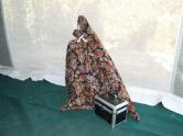
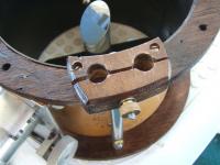
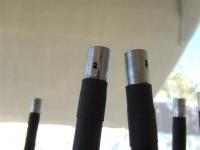
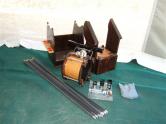
While I was at it I made a ‘”T” handled spanner for a short piece of Allen key wrench and press fitted that into the end of the T bar (as we like to call these home made tools). When I set up the telescope the parts are in a special box (along with a few spares, haven’t lost any screws yet, it just proves that if you have a spare you will be unlikely to need it!). Some would say (and I would agree, but…) that with this type of telescope you should have all things that can fall on to the mirror firmly attached to the setup! True, but in this case I NEVER remove the mirror box cover until I start viewing, well after assemble is complete. The secondary cage does have captive everything! A clamp was made from ply and two holes drilled 12 mm in dimeter side by side. There was enough room in the clamp to drill a 4mm hole at ninety degrees, between the two 12mm holes. The wooden “clamps” were then cut in halves to separate the now undersize 12 mm holes. Best you look at the pictures to see how this works. See image below. One half of the clamp is screwed and glued to the bottom of the secondary cage, and the bolt and knurled nut that helps perform the clamping action has its end burred over so the nut cannot fall off down on to the primary mirror. The clamping screw holds the unsecured part of the clamp in situ and is always ready to clamp the tube ends.
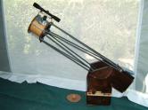
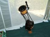
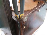
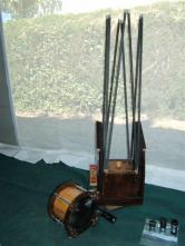
The altitude bearings are 2 pieces of round (19 mm) Teflon bearing on slightly textured Laminex (actually Laminex pre-glued edging) strip, and they work smoothly and when the telescope’s altitude is altered no bounce is noticed. The azimuth (3 off at 120° apart) bearings are also Teflon but a bit larger in size and they ride on the same Laminex on the underside of the assembly. This works quite well and the ‘scope stays where it is put without any protest or effort. Assembly and CollimationAssembly involves attaching the tubes to the primary mirror box. The tubes and the mirror box are numbered 1 through 8 and the numbers are always aligned to each other (see image below). The crushed ends are also painted yellow (see image of truss tube attachments above) so when I assemble these to the Mirror box, the colour always faces out. It ensures alignment is always as easy and reliable.
The secondary cage is also numbered 1 to 8 and each is aligned so the numbers stamped on the end of the tube correspond to the numbers printed on the clamps. The secondary cage clamp screws are wound out fully until the clamp is as wide as the bolt will allow. The secondary cage is offered up to the ends of the tubes aligning the numbers and tubes with the holes in the clamps. Holding the secondary cage down on to the ends of the tubes, allows the tightening of the clamp nuts and when this is done the whole thing is a s rigid as can be, no twisting at all, very clever See Photo 8. Collimation is very quite straight forward and involves aligning the secondary mirror first (only done rarely) and then twiddling the wing nuts one way or another to align the primary mirror (See mirror box above, and image below) I have made gadgets to help with this but it is so easy to do by eye I don’t bother with the gadgets. Occasional I use them just to double check my eye accuracy but it is only a check. One of the last things to do was align the “Finder” scope. This has proved to be troublesome part of the design and it is my own fault. I intend to change this idea for something lighter, but when it works it does so well. It was an old rifle telescopic sight and it has a respectable optic size and 7 times magnification, some of the reasons I have persevered with it. I found a distant tower and then set about aligning the finder to the telescope. Several shims and some twisting had the cross hairs corresponding to the centre of the primary mirror.
In UseAt last. How good will it be? Compared to What? Surprisingly the optics are very clear and detail in the planets and moon was clearer than the 200mm telescope. Mind you the mirror finish in the bigger scope was fairly awful. The star views tend to lack impact or should I say resolution? (for the want of a better description) but I have seen some stunningly good sights in my travels just the same, especially in Central Australia. The underlying problem behind all this is that I would like a larger mirror, but that was not the brief. I wanted a telescope that could let me carry on viewing the stars while travelling and also show anyone who was interested views of some stars and whatever planets happened to be around at viewing times. That aspect of viewing is always very rewarding when you hear the reaction of folks who see Jupiter or Saturn for the first time. This tool achieves its objectives in fine style. Actually the more I use it the more enjoy it. I guess that is the bottom line! Assembly and dis-assembly are quick and trouble free, and it does stow away in the caravan or the back of the car easily. The telescope is performing as planned actually better than I expected and quite a number of people have enjoyed gazing at the heavens.
ConclusionI am glad I did build this telescope, and for only a small outlay of money. Would I recommend any one to build their own scope? Positively yes. BUT as an exercise in learning about telescopes. However, from a financial point of view, no. It is now very cheap to purchase Dobsonian telescopes off the shelf, and fully equipped with lenses and finder scopes. $450 will buy a new 150mm (6 inch) telescope. At that price it is hard to justify building one. Who would ever have thought ten years ago you could buy a 300mm (12 inch)Truss Tube telescope for around the $1200.00? The primary mirror alone was around that price! My next scope will be a Scmitt-Cassegrain type, at least 300mm in diameter, home built? I have the capability but not the desire, yet! From a financial point of view it may be too uneconomical. Post scriptSince writing this article I have built an adapter to house my green laser pointer and removed the telescopic site. What an improvement that has been. The mounts are nothing fancy being similar to the mounts often found on finder scopes as used on many telescopes. Put the green beam on what you want to see and look in the eye piece, too easy. I can thoroughly recommend green laser pointers. Article by Peter Pocock (Papa Oscar). Discuss this article on the IceInSpace Forum.  |
|
|||||||||||||||||||||||||||||||||||||||||||||||||||||||||||||||||||||