ICEINSPACE

|
Collimation and the Newtonian Telescope
Submitted: Tuesday, 10th April 2007 by Don Pensack
“If I have seen further it is by standing on the shoulders of giants.” - Isaac Newton The telescope most likely to need collimation is the Newtonian reflector (which includes Dobsonians) because it is most likely to have its mirrors knocked out of alignment by handling, travel, and/or reassembly at an observing spot. Collimation is the alignment of the optical parts of a telescope. Though lining up the secondary under the focuser is essential for uniform illumination of the field of view, there are only two critical alignments in Newtonian collimation: the Focuser Axis (aligned by adjusting the secondary mirror), and the Primary Axis (aligned by adjusting the primary mirror). These must be lined up to produce high-quality images, but the necessity of doing so becomes more critical the shorter the focal ratio of the scope. To wit, the tolerance for primary mirror axial error (PAE) is usually given as .005mm x the f/ratio cubed. Since that cubed figure goes down rapidly as the f/ratio diminishes, you can see that excellent collimation becomes a necessity with shorter f/ratio scopes because of rapidly decreasing tolerances for miscollimation. At f/6, that tolerance calculates to 1.08mm at the focal plane, but at f/4.5 only 0.46mm. Techniques that work fine with the loose tolerances of long f/ratio scopes simply aren’t good enough to provide the best possible images in short f/ratio scopes. Improvements in technique are necessary, and that is one of the purposes for this article. Fortunately, the same techniques for collimating the short focal ratio telescope can be equally well-applied to longer focal ratios, so the techniques you learn for one can be used for the other. [Though the purpose of this article is not to discuss coma, but collimation, it is illustrative to note that the coma-free field of view in a Newtonian reflector is figured at .0007 inches times the f/ratio cubed (e.g. 0.0875”, or 2.22mm, on an f/5 scope)*, and a very slight misalignment of the optical axis can have a devastating effect on the very presence of any coma-free field in the eyepiece! *Everhart’s less stringent calculation is .022mm x the f/ratio cubed. It still results in a small coma-free field, but slightly larger than the one quoted above from Sinnott, et.al.] The reason I mentioned coma is that if a TeleVue Paracorr coma corrector is added, the maximum allowable tolerances for miscollimation of the Focuser Axis (Focuser Axial Error, or FAE) reduce to 1/6th the allowable miscollimation without the corrector [FAE tolerances are usually given as .03 times the diameter of the primary in millimeters--this becomes .005mm times the primary diameter with a Paracorr], so learning the techniques for collimation of the focuser axis to a couple hundredths of an inch is critical with shorter f/ratio telescopes, which typically do use a coma corrector like the Paracorr. What happens if the scope is not collimated? At the very least, the position of best focus will not be located in the center of the field of view. At worst, every star in the field will display a flaring away from a poorly focused image that resembles a small comet. Extended objects, like the Moon or planets, will have details “smeared” out and focus will be nearly impossible to achieve. A very small miscollimation can introduce visual effects exceeding ¼ wavelength of aberrations, the maximum allowable error before the image deteriorates to less than the aperture should display. What follows is a description of how to collimate accurately to a level where collimation errors no longer influence the image quality. THE TOOLS OF COLLIMATIONThe most commonly used (there are other exotic, do-it-yourself tools that also work, but they are uncommon) Newtonian collimation tools are:
What follows is a couple of pages illustrating the 2 most common alignment protocols in Newtonian collimation. Note that both illustrations show telescopes properly collimated, and, presuming the opening at the front is not too small, neither protocol provides superior collimation but one may be easier to achieve easily. I include the illustrations here so that the reader can refer back to them during the article that follows. [More on that later].
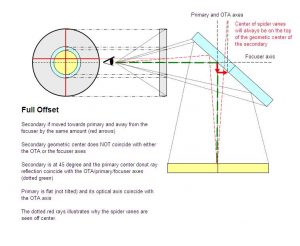
THE BI-DIRECTIONAL OFFSET ("CLASSICAL" OFFSET) COLLIMATION ILLUSTRATED
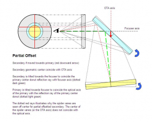
THE UNI-DIRECTIONAL OFFSET ("NEW MODEL") COLLIMATION ILLUSTRATED
Simple Definition and Step-By-Step Procedures of Collimation (a summary of the following article):Collimation is the alignment of the optical axis of the primary mirror to the focuser axis (utilizing tilt adjustments on both mirrors), so we start out assuming the focuser is tight on the tube and relatively square to the tube axis. The entire procedure can be and is easier done in daylight. A bright sky is useful to allow us to see all the necessary reflections. [Disclaimer: I have no monetary interest in Catseye Collimation, and I use examples of their tools (with permission) to illustrate the techniques of collimation simply because I feel they are the best tools that money can buy to achieve collimation in today’s Newtonian reflectors, whatever the focal length. All these tools could be homemade by any decent machinist, but why reinvent the wheel?] First, start by centering the secondary from side-to-side in the telescope’s tube. Use a piece of cardboard or some other indicator to make sure the secondary is equidistant from the tube walls in both the focuser and perpendicular-to-the-focuser axes. You may have to adjust the spider vanes supporting the secondary mirror to accomplish this. Note that this step automatically assumes we will be using the Uni-Directional Offset alignment protocol, which is the method explained in the steps to come. Then follow the steps described below. THESE STEPS ARE DONE IN A-B-C-D ORDER.
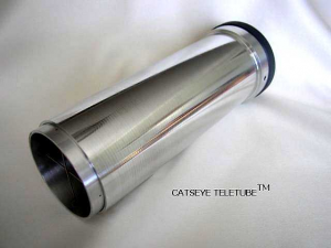
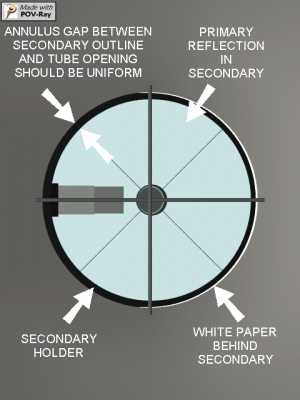
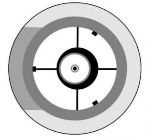
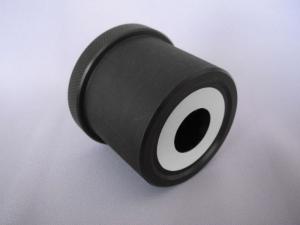
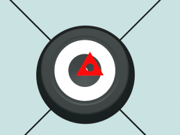
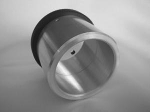
STEP A Aligning the Secondary mirror under the focuserThe tool used is the Sight Tube, a long cylinder with crosshair wires at one end and a peep-hole at the other. The Sight Tube is inserted in the focuser until the outline of the inside diameter of the sight tube appears to surround the outside diameter of the reflective surface of the secondary mirror, and then is fastened tightly in the focuser with the setscrew. The Catseye TeleTube pictured above is adjustable in length to help you do just that, as well as guarantee the proper alignment without parallax-induced errors. If you can’t tell where the edge of the secondary mirror is, hold a piece of white paper against the inside of the tube opposite the focuser. This will surround the secondary mirror with a white background, making it easy to see where the edge of the mirror is. The goal is to make the outside edge of the secondary mirror appear concentric with the inside diameter of the end of the sight tube, as seen through the peep hole. Start out by rotating the secondary on its center bolt until it appears round to the eye when viewed through the peephole of the sight tube. It may be necessary to reach inside the tube and gently grasp the outside of the secondary holder to do this. If the secondary is merely cemented to a stalk and is not in a holder, to avoid the risk of loosening the cement bond, you may want to slightly loosen the 3 collimation screws on the secondary mirror first so it is not so difficult to turn. If the secondary appears too far up the tube, away from the primary, its center bolt will need to be loosened and the secondary lowered in the tube toward the primary, or vice-versa. Do this with the tube nearly horizontal to avoid the possibility of dropping a tool (or secondary mirror!) on the primary mirror. Once the mirror appears to be centered in the up-tube/down-tube direction, it will need to be moved until it is centered in the side-to-side direction. This does not have to be exact, but if it appears oval, even slightly, rotate the secondary until it appears round. Then, carefully use the screws on the secondary to make the round image of the secondary appear concentric with the inside diameter of the sight tube. [This last assumes the secondary center bolt is already at the center of the tube, as measured from each side. If it is not in the center of the tube, you should adjust the spider vanes to center the mirror before you start on Step A.]. Alternately, you can adjust the tilt of the focuser to accomplish this, but this is often more difficult to do than simply adjusting the secondary screws to center its reflective surface under the focuser. As an aid to proper rotational alignment of the secondary, making the reflected image of the primary mirror appear centered on the secondary's reflective surface is a good starting point. In fact, making the 3 circles concentric before doing final collimation of the secondary tilt gets you most of the way toward collimation in the scope. Essentially, you adjust the rotation and tilt of the secondary so the reflected image of the primary, the outside edge of the reflective surface of the secondary, and the inside edge of the sight tube are all concentric. It helps to move the focuser in and out until all three circles are similar in size to enable better visualization of concentricity. This will only have to be done once, though in initial collimation you may have to repeat it a couple times after doing the next step, so take your time to make it right. If moving it sideways to center its outline in the sight tube makes the secondary appear non-round or oval, rotate the secondary on its center-bolt until it appears round again. See the following diagram of the appearance of a properly positioned secondary in a collimated scope as seen through the sight tube. This is what you will achieve.
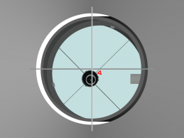
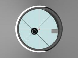
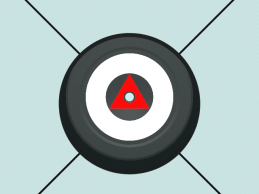
Here is the same view with a slightly smaller secondary in the view to emphasize the lack of concentricity of the secondary mirror reflection shadow's outline to the other images. The dot is centered, and the sight tube’s crosshairs are removed to make it clearer that the crosshairs do not cross the image of the secondary reflection in exactly the same way as the reflected spider vanes. This is a slight exaggeration of the appearance through the focuser in the “Uni-Directional Offset” collimation (more on that later), but serves to illustrate the secondary shadow's reflected outline does not appear concentric in a properly collimated shorter f/ratio (<f/6) telescope.
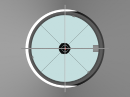
STEP B Aligning the focuser axis by adjusting the tilt of the secondary mirror (which is what we are really doing when we adjust secondary mirror tilt)The tool used is the Sight tube, the point-source red laser collimator, or the Combination Sight Tube/Cheshire tool. The laser must itself be collimated or using it will misalign the scope. Many low-cost lasers come out of the box uncollimated. It is primarily for this reason I prefer the sight tube. Insert the sight tube and fasten the setscrew tight. Look at the crosshairs through the peep-hole and note the position of the distant center marker on the primary mirror* [*if the primary mirror does not have a center marker, you will have to remove the mirror and put one on it. If you don’t know how to do this, have a local shop or astronomer friend help you out. You cannot successfully collimate without one. A transparent mirror center-spotting template such as the ones available from Catseye (for all mirror sizes) and FarPoint (for mirrors under 15") allows a home user to perfectly position the center dot to less than 0.02” (0.5mm), which is accurate enough for good collimation. If the mirror already has a center dot, it's position should be checked—some come misapplied and off-center as much as ¼” (6mm).] Carefully adjust the collimation screws on the secondary until the Primary's center marker appears lined up exactly behind the crosshairs’ intersection. What you’re doing in this step is to tilt the secondary mirror to point the reflected focuser axis directly at the center of the primary mirror. That’s why we’re adjusting the secondary mirror. This may move the round image of the outline of the secondary out of concentricity with the inside diameter of the sight tube. If so, repeat Step A and then Step B again. Each iteration brings the secondary closer to exact alignment. If you have to choose between having the center marker + crosshairs line up, or having the secondary be centered under the focuser, pick the center marker’s line up with the crosshairs. The centering of the secondary mirror in the focuser is only to provide even illumination of the image all the way around the edge of the field of view—less important than correctly adjusting the optical reflection from the secondary mirror with regard to the focuser axis. [If you have a lot of light in the tube, or the sky light illuminates the bottom of the Sight Tube’s crosshairs, a distant reflection of the underside of the crosshairs will be visible, but will appear a lot smaller than the near-to-the-eye crosshairs in the tool (which appear dark because they are not lighted on the side nearest the eye). When the telescope's primary is collimated, this distant reflection of the crosshairs will be hidden behind the near-field crosshairs. This distant reflection of the underside of the crosshairs is removed for simplicity in the BEFORE image that follows.] Some people have trouble focusing on the center mark and the crosshairs at the same time. It helps to use glasses in that case, or back the eye up far enough to allow both to be in focus. Even if the crosshairs are slightly out of focus, the diffraction put up by the crossing of the hairs creates a “dot” in the vision that can be lined up with a center mark that has a hole in it. If you back away from the sight tube, hold on to the scope or focuser with one hand—this steadies the body and the eye so you won’t be bobbing back and forth trying to see the image through the peephole. If a laser is used, the secondary mirror’s tilt is adjusted until the laser beam hits the center of the Primary’s center dot. It should be noted that this is adjusting the secondary to the focuser axis, but it does not adjust either rotation or centering of the secondary relative to the focuser. To accomplish this, it’s still necessary to use a sight tube. Since adjusting the tilt may move the secondary off-center relative to the focuser, you may need to check again with the Sight Tube. This step essentially aligns the secondary to the focuser axis, so that moving the focuser in and out (as in focusing) will make no difference in collimation.
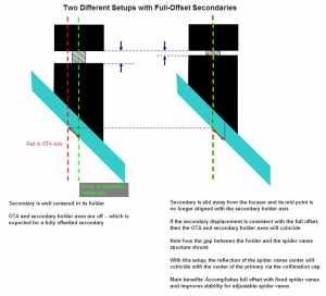
AN ASIDE ON SECONDARY MIRROR OFFSET: THE OLDER BI-DIRECTIONAL, “CLASSICAL”, VERSION VERSUS THE UNI-DIRECTIONAL, "NEW MODEL", VERSION OF OFFSET ( A discussion of the two earlier illustrations)You may have read that the secondary mirror has to be “offset” in the tube in order to center the optical system on the mirrors and result in uniform illumination of the field of view in the telescope. This is automatically accomplished by following the collimation steps in this article, so the discussion of Offset that follows is only an aside for those curious about how offset is accomplished, and how the two “models” differ: If the focuser is not perfectly perpendicular to the tube, it doesn’t matter for collimation except that the optical axis may not EXACTLY coincide with the mechanical center-line of the tube. Indeed, this lack of coincidence of the optical and tube axes is one of the consequences of secondary mirror “offset” when using the Uni-Directional Offset “New Model” protocol (wherein the secondary mirror is offset only in one direction--the up-tube/down-tube direction--to center the secondary mirror under the focuser wherever it points); and it could be so also when using Bi-Directional Offset (“Classical Offset”, which entails moving the secondary away from the focuser slightly as well) if the focuser is not exactly “square” to the tube. In fact, if Bi-Directional Offset is used, the Optical Centerline and Mechanical Centerline can coincide only if the focuser is perfectly perpendicular (“square”) to the tube. [Note that in order for the movement of the Newtonian scope to be strictly accurate in coinciding with the center axis of the tube, the optical and mechanical axes must be strictly perpendicular or parallel (and other mechanical inaccuracies must be nearly perfect).] The best we can achieve is near-perfect alignment, and fortunately, that is good enough. With Uni-Directional Offset, the Optical axis will be ever-so-slightly tilted toward the focuser. This will make literally no difference at the eyepiece, but MAY make a difference to certain brands of digital setting circles (DSC) used in certain conditions. Note this offset is very small, and is less deleterious to the accuracy of a DSC than inaccurate centering of the alignment stars. Nonetheless, it’s real and may affect DSC accuracy. The advantage of Uni-Directional Offset is that the secondary remains centered in the tube and appears centered under the focuser. Both conditions can be achieved at the same time, and easily. Bi-directional offset requires calculations. What follows is an illustration with 2 different versions of Full Offset wherein the secondary is also offset away from the centerline of the optical tube (they are two different ways of achieving "Classical" Offset). Note that Uni-Directional Offset, which is the technique described in this article, does not require the mechanical offsetting of the secondary that shows in the illustration, yet results in the same full offset relative to the optical centerline when the scope is collimated. The left illustration shows the entire secondary and holder offset bi-directionally, while the right illustration shows the "Classical" way of doing it, wherein only the mirror is offset. Since it is simpler to accomplish, it is Uni-Directional Offset which has been described in the collimation procedures in this article. This is here primarily to show that there is more than one way to accomplish Bi-directional Offset collimation.
Note that in Bi-Directional offsetting of the secondary mirror it is dropped toward the primary mirror and moved slightly away from the focuser. This keeps the mechanical center axis of the tube coincident with the optical axis of the telescope. The secondary will no longer be centered in the tube from side-to-side. THE MODERN UNI-DIRECTIONAL OFFSET COLLIMATION PROTOCOL (Exaggerated)--refer back to the full size drawing earlier in the article. Note that in UNI-DIRECTIONAL OFFSET of the secondary mirror mechanical offset is only done toward the primary mirror and this results in a slight tilt of the optical axis away from the centerline of the tube. It is a tiny amount and *barely* makes a difference compared to BI-DIRECTIONAL OFFSET. But it is much easier to accomplish for the user because the secondary mirror stays centered in the tube. Since both techniques result in full offset of the secondary mirror, yet one is easier to achieve, it is UNI-DIRECTIONAL OFFSET that is recommended.
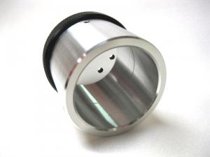
STEP C Aligning the Primary mirrorThe tool used is the Cheshire eyepiece (The Catseye Black Cat is pictured above), or the barlowed laser, or the focused Krupa collimator, or the combination sight tube/Cheshire tool. A Cheshire eyepiece is either a cylindrical tool with a hole in the side of it and an internal 45-degree mirror to reflect light from the sky down onto the primary mirror and back or an even-simpler tool with a bright ring on the bottom and a simple peep hole on the other end (pictured). Be careful when you insert a 45-degree Cheshire like the Tectron or most combination tools on the market (the type with an open window on the side) that you do not cover the side hole with the bill of a cap so the 45 degree surface can reflect the bright light of the ceiling or sky; for the simpler bright ring type (pictured), the tool should be fully inserted. What this tool provides, when viewed through, is a reflected bright ring with a dark center. Use the collimation screws on the Primary mirror to move the reflected image of the center marker into the dark center of the bright ring of reflected light. It may be necessary, if a lot of movement is required, to repeat Step B for the Secondary mirror, and then repeat Step C (this is usually only necessary when a scope is assembled from components or a major shift in primary alignment follows disassembly of a mirror cell for the replacement of springs). In a properly collimated telescope both secondary and primary alignment will agree at the same time. If a combination tool is used, the crosshairs, center dot, and dark center and reflected crosshairs will all line up at the same time. If a barlowed laser is used, the reflected red beam will have a dark shadow of the reflected center marker that you will center on the open hole at the bottom of the Barlow. This alignment is just as accurate as a Cheshire, and some would argue less intrinsically plagued by parallax—presuming, of course, that you can even see the bottom of the Barlow from the bottom of the focuser. I will not describe the Barlowed Laser Technique, here, even though it is as accurate as a Cheshire used properly because you cannot see the image on the bottom of the Barlow on-axis and because a typical Barlow does not enter the focuser deeply enough to have its bottom visible (except in large scopes with low-profile focusers). Addendum: Devices now exist to allow the bottom of the Barlow to be seen from either the front of the scope or the bottom of the scope easily, inside or outside the focuser drawtube. The only possible downside to these would be possible registration errors cause by a multiplicity of devices inserted in the focuser, each with its own possible registration error. When this step is done, the primary’s optical axis will be pointed at exactly the same point on the secondary mirror the eye sees the reflection of the primary mirror’s center mark. If a perfectly collimated single point laser is used, the return beam will accurately track the outward beam to its source. However, a single beam laser can return its beam to the source with errors in mirror placements and tilt, not to mention the difficulty of the accuracy assessment, so if a laser is used, the Barlowed laser technique is strongly recommended for primary mirror alignment.
If you have been careful, any Newtonian will be well collimated at this point in the procedure, but, for the users of f/5 scopes and shorter, or for the users of longer focal ratio scopes who want absolutely perfect collimation, some improvement can yet be made.
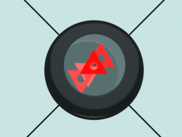
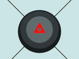
STEP D Eliminating any visible residual errors with an AutocollimatorNo, it doesn’t do the work for you, despite its name, but it allows you to see tiny misalignments of the mirrors and correct them to a high degree. On short f/ratio scopes, where the allowable tolerances for miscollimation are in the thousandths of an inch, such a tool is essential. This tool is so sensitive to misalignment that simple mechanical flexures will be visible (i.e. in the focuser, tube, mirror spider, primary springs, etc). If your secondary spider vanes are too loose, the telescope will not hold collimation to a few thousandths through all the altitude changes the telescope goes through, so the first thing to do is to tighten the screws that hold the secondary spider to the tube. Be careful! Though they should be quite tight, most of them are small screws that can be stripped if applying too much force. Most commercial scopes come with these screws quite loose, however, and tightening is almost always called for. Be careful that tightening the spider screws does not start to pull them through the tube. I had to add fender washers under my spider’s screw heads in order to get the spider vanes tight enough. If the spider is tight enough, you will not see any collimation changes in the sight tube or simple beam laser with a change of altitude of pointing on the scope’s tube. The Autocollimator is inserted and tightened in place. This is a tool with an internal flat mirror that faces the secondary mirror. As you can guess, when alignment is achieved, there is no light in the peep-hole and the whole field goes dark. Because four images of the mirror’s center marker will be visible against this darker background, and each reflection comes from a different number of reflections between the primary mirror and autocollimator mirror, you are essentially collimating the telescope at multiple focal lengths of your telescope and lining up all those collimations into one. If done carefully, collimation will be accurate to a small number of thousandths of an inch—accurate enough for even an f/3 telescope. This accuracy rewards the observer with the best possible images that can be had with the scope. When looking in, there will be four images of the primary’s center mark, each one slightly fainter than the next. The 4th (actually, since one is seen directly, it's the 3rd) reflection is often difficult to see if you do not have enough light in the tube. This is why I recommend using a daylight sky as your collimation “target” when doing initial alignment. if you can illuminate the center marker brightly enough, all four images of the center marker can be seen at night as well. If your previous steps were carefully done, these 4 images will be overlapped or nearly “stacked” on top of one another. But, if all 4 are seen, better alignment can be achieved. By carefully moving the secondary and primary collimation screws, the four reflected images of the center mark will stack tightly on top of one another. Two of them will disappear (if a triangle is used the ones that point the opposite direction than the brightest and sharpest image, so you will see only one triangle when all images are stacked). It is imperative to return to the Cheshire at some point and check alignment of the primary. If it’s off, correct it in the Cheshire (turning the primary collimation screws), and return to the autocollimator. After a couple times back and forth, all four images of the center mark will “stack” tightly on top of one another, and your telescope will be perfectly collimated. Tiny changes in secondary tilt affect the primary’s optical axis, so it’s essential you go back and forth between the autocollimator and Cheshire. Both tools have to agree at the same time to achieve collimation.
The next time the telescope is taken out, collimation Step A above will not need to be done. It’s probably not a bad idea to check the alignment of the secondary with the sight tube, but it is unlikely that more than a minor tweak of one screw will be necessary. Then, proceed to Steps B and C. If you use an autocollimator, skip Step A and start with Step B. The autocollimator will perfectly align the secondary in Step D. IMPORTANT NOTE ON AN EASIER METHOD OF USING THE AUTOCOLLIMATOR: The final step of stacking the 4 images of the center mark can be made easier if the “Carefully Decollimated Primary” (CDP) protocol is followed. In essence, when the images are nearly stacked, one collimation screw on the primary mirror is purposely loosened to decollimate two of the 4 stacked images, i.e. they swing away from the “stack” into the outer parts of the field of view in the autocollimator. The two that remain nearly stacked are easily stacked perfectly with minor adjustments of only the secondary mirror’s collimation screws. Then the two separated images are brought into the stack by adjustment of only the primary mirror. This technique is described in great detail on the web at Catseye Collimation. [Go down the left side of the page to VIC MENARD'S CDP PROTOCOL to see a description of this process with pictures] MECHANICAL IMPROVEMENTS TO HELP HOLD COLLIMATION FIRMLY:All your efforts will be for naught if the mechanical structure of your scope is incapable of holding the collimation (you’ve achieved) as the scope changes in altitude or attitude (I included a note about the tightness of the spider earlier). If you notice a change in collimation with the movement of your scope, here are some things to check: 1. Mechanical tightness of the secondary spider. Since the secondary hangs below the spider when the tube points up, and beside it when the tube is horizontal, this off-center weight is quite able to impart a twist to the secondary’s spider vanes, which causes changes in collimation. To fix this one, make sure the spider is VERY tight (it should emit a high pitch if tapped with a finger). If tightening the spider vanes this much would cause the spider attachment screws to pull through the tube, then install large diameter fender washers under the heads of the screws to distribute the force over a larger area or put braces outside the tube. Some curved spider vanes cannot be made tight enough to hold position that well, one of the possible drawbacks of curved spider vanes. 2. Mechanical movement of the primary mirror. If the spring stiffness is insufficient to hold the primary mirror in place, then the primary mirror may tilt forward when the tube points at low altitude. Some telescopes compensate for weak springs by installing locking bolts that hold the mirror in place once collimation has been achieved. The problem with locking bolts is that tightening them will change the collimation, so final collimation must be done with the locking screws rather than the collimation screws. I strongly recommend eliminating the locking screws and changing the springs to very stiff springs capable of holding the weight of the mirror without movement. Not only will this make collimating easier, but it will insure that your collimation will hold. Of course, for any spring to be able to hold the mirror in place, it should be compressed nearly all the way as well as be very stiff on its own. Springs like this are available at a lot of better hardware stores or from McMaster-Carr online. Bellville springs, coil springs, and even urethane bushings can be used. 3. Sag in the focuser. Needless to say, if putting an eyepiece into the focuser causes the focuser drawtube to change angle, then collimation is immediately off. At the very least, the focuser should be adjusted to provide as close to zero “slop” as possible. A good focuser will not change the collimation as it moves in and out. If yours does, then an overhaul or replacement of the focuser is called for. Quality focusers (as of this writing) start under $100, so if you intend to keep your scope for a while, this expenditure is quite justifiable. A NOTE ON LASER COLLIMATORS AND CATSEYE TOOLS:Because there are only a couple brands of lasers that come to the purchaser collimated, I do not recommend the use of a laser unless you are willing to assume the responsibility of collimating the laser once it arrives. Even if collimated, the stock simple-beam laser is only truly effective at collimating the secondary mirror to the focuser axis. A simple Cheshire is more effective at achieving primary mirror alignment because the return beam of the laser is too large (and unlikely to have hit the center of the primary with sufficient accuracy to make the return beam precise enough) to allow the same precision of alignment as passive tools [special exception: the Barlowed Laser Primary Alignment, which is as accurate as the Cheshire tool previously described]. And since the sight tube is necessary to initially align the concentricity of secondary mirror and focuser, I fail to see the necessity of a laser in collimation unless you have no choice but to set up in complete darkness. Even then, a bright red LED flashlight aimed at the primary mirror’s center mark will make collimation possible and easy with the three passive tools described above. There are some people who have great difficulty focusing on the near-field crosshairs of the sight tube and the primary center mark at the same time. They find the use of a laser easier. Indeed, if you have a truss-tubed scope, you can get your eye close enough to the primary to see the beam hit the mirror from up close, and that will greatly increase the accuracy of your positioning of the laser beam dead center in the primary’s center mark, but if you have a full-tubed scope you cannot do so. Plus, most lasers’ beams do not hit the mirror with a tiny point, but have beams shaped like an oval or dash. Estimating the center of the primary mirror’s center mark to better than 1/50th of an inch (and even less if you wish to use the return beam of the laser for collimation) is just, simply, highly unlikely with such a beam.
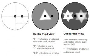
If you have an XLK autocollimator (a newly designed AC with 2 holes in it for different points of view of the stacked images—note: in the picture above the two holes appear off-center--in reality, one is centered) then either method (passive or laser) will get you close enough to refine the alignment of the secondary-to-focuser axis closely enough for the AC to eliminate residual errors. But if using a standard, single pupil, autocollimator, I still prefer to start by using the passive tool (sight tube) instead of a laser. If you choose to use a laser, start with one that has a small beam spot (small aperture stop) and will require no collimation on your part to be useful as a collimator—at this writing, Howie Glatter and FarPoint lasers satisfy that requirement. Catseye collimation tools now have been upgraded with a smaller peep-hole (only 2.5mm (0.099”) than the originals, in order to enable a better centering of the eye when looking through the tools (to reduce parallax--the change of viewpoint when the eye can shift back and forth when looking through the tools, which can give different perspectives and make exact collimation more difficult). These tools, labeled “XL” are a little easier to use for those of us with small daytime pupil diameters and who don’t wear glasses to focus at the distance of our mirrors from the eyepieces. Outwardly, they are similar to the originals (though the Black Cat XL and Infinity XL are a bit longer and insert a little deeper in the focuser), but they do function a little differently. I, as one user, have found the XL tools easier to use and achieve alignment with. I find the Infinity XL (autocollimator) requires me to do less fiddling when stacking the 4 reflected images of my primary’s center mark because the TeleTube XL and Black Cat XL get the alignment a little closer before I switch to the Infinity XL to eliminate the residual errors. The autocollimator (Infinity XL) has been improved even further with the addition of a second hole (the Infinity XLK) to allow viewing the 4 stacked images as two stacks of 2 (see illustration below). This tool is a step up in accuracy from the standard autocollimator, and I recommend it. I find that what appears as a “perfect” stack of the 4 center mark images in the standard autocollimator can be refined even more by using the XLK version. Here is a picture of the images of the “stacked” center marks in the two pupils of the XLK autocollimator, courtesy of Ghassan “Jason” Khadder, whose influence inspired the XLK tool:
You may find (I certainly do) that stacking the two sharp images on the left (in the illustrated orientation) in the offset pupil of the 2-pupil tool is easier than to achieve a perfect stack using a sight tube or the P+3 reflections (see reference to CDP procedure) in the center pupil of the autocollimator. The reason is that the P+2 stack in the lateral window of the XLK autocollimator is uncluttered with the slightly fuzzy and a bit out of focus 1+3 reflections, and so can be aligned to a higher precision. This can eliminate any residual FAE (focuser axial error) if you move back and forth between the AC and a cheshire to verify primary alignment (the cheshire eliminates Primary Axial Error (PAE)). I have never failed to find a tiny misalignment showing in the lateral pupil of the XLK autocollimator even after using the Carefully Decollimated Protocol (CDP) to carefully line up secondary and primary reflections in the central pupil of the autocollimator. Since the P+2 reflection lineup done in the lateral pupil of the XLK autocollimator only insures the optical axes of focuser and primary mirror are parallel, it is necessary to go back and forth with the cheshire tool until the P+2 reflections in the XLK and cheshire primary alignment agree completely at the same time. When the P+2 reflections in the lateral pupil, the 4 stacked reflections in the central pupil, and the primary alignment in the cheshire all agree, you have achieved the best alignment your scope allows, given mechanical constraints. If you use the 1-pupil autocollimator, you will see the center image when you are done. I repeat that I have no commercial interest or business association with Catseye Collimation. I simply recommend them as the best passive tools currently available, whichever version you may use. Their usage will result in collimation to tolerances previously unachieved and which have become a necessity in the current market of super-short f/ratio scopes. I also hope that this article has given you some insight into collimation, and will help you achieve the best images your scope can deliver. Article by Don Pensack with illustrations/pictures courtesy of Jim Fly and Jason Khadder. Discuss this article on the IceInSpace Forum.
 |
|
|||||||||||||||||||||||||||||||||||||||||||||||||||||||||||||||||||||||