ICEINSPACE
|
Moon Phase
CURRENT MOON
Waning Crescent 30.2%
|

|
 |
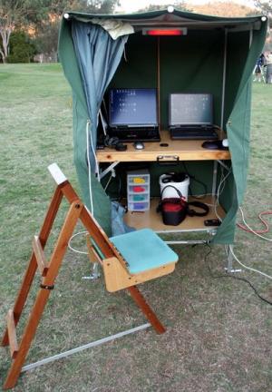
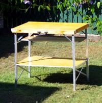
A Portable, Dew-Proof, Astronomy Hutch
Submitted: Wednesday, 21st February 2007 by Dennis Simmons
This is an article on how I designed and built a collapsible, portable observing hutch.
|
 |
|
Click to Enlarge
Astronomy Hutch
|
IntroductionDrip, drip, drip…the dispiriting drip of damp dew drops drenching my treasured Hartung’s 2nd Edition and Norton’s Star Atlas, dripping from the roof of the makeshift wooden crate that housed them became intolerable. I determined I had to find a better solution for keeping my books and charts dry under the humid summer time night skies of Queensland. I decided to build a covered, portable observing table that would protect my books and charts as well as provide some storage space for eyepieces and other accessories.
I designed and built the original observing table in the days of yore, long before CCD’s and computers appeared on the amateur astronomy scene. The original covered table has since evolved to become a portable hutch, designed to keep computers dry, eyepieces to hand, provide storage space for binoculars, cameras, batteries, cleaning equipment, mains adapters, lens caps, etc., keep equipment organised, mains power available, cables neatly routed and star charts dry, as well as satisfying human engineering considerations (astro-ergonomics).
Oh, and I also required the capability to throw impromptu evening tea and vegemite toast parties, for those special occasions when my darling wife pads down the stairs to join me once the Planets and the Moon become visible at respectable hours!
Although the original observing table was designed and built in the paper era, the design was sufficiently flexible for it to evolve to meet the more challenging requirements of the equipment rich, power hungry digital era, so I’ll describe the hutch as if I had built it with digital astronomy in mind. The HutchI’ll provide you with some rough measurements and guidelines should you wish to build one for yourself. I have steered clear of giving comprehensive measurements with prescriptive, detailed step-by-step instructions, so that each person may build something more suited to their needs rather than try to fit in with mine. I have included several photos of the structure, and components, to help with the construction.
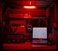
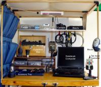
Figures 1 & 2 illustrate the top work surface and typical equipment payload of the hutch, as viewed during the night and in the daytime respectively. Relax - the red light night photo was a 10 second exposure, greatly exaggerating the light output!
|
 | |  |
Click to Enlarge
Fig 1 - Nighttimes action
|
|
Click to Enlarge
Fig 2 - Daytime view
|
Planning PhaseInitially, I spent a few weeks just thinking about the requirements in terms of what the hutch had to do, before I commenced the detailed design. This thinking process provided me with a comprehensive wish list as follows:
Requirements
- Two large work surfaces required - one (upper) for working on, the other (lower) for storage.
- Capacity to add further shelves if required, as storage requirements continue to rapidly grow with new equipment acquisition.
- Largest possible working surface area, within the constraints of handling, set up and transportability. I don’t enjoy working in cramped conditions.
- When packed, should easily fit into a small to medium sized motor vehicle.
- One person carry-out and set up.
- Easy to set up at night with a red light head torch.
- Easy to erect - less than 5 minutes for an experienced user.
- Simple, no-tool erection - no fiddly nuts and bolts that can be dropped, forgotten or lost.
- Built in, mains powered red light illumination for the upper working area.
- Stable in windy conditions.
- Comfortable to use when standing or seated.
- Multiple power points with ELCB protection.
- Front opening overhang to provide protection from exceptionally heavy dew.
- Front curtain to minimise PC light pollution, protect equipment from dust and keep hutch closed in day time.
- Self-contained; all pieces to stow away in collapsed table if possible. Too easy to forget stuff!
- Manoeuvrable when fully assembled, to allow for re-positioning in the field depending on where I am imaging. This allows me to avoid thermals from my body impinging on the light path when imaging.
- Be showerproof.
Note that some of these requirements emerged later, during the construction phase as the unit took shape and I was able to get some feedback from the construction process.
Basic Design
- Tabletop to be 900mm x 600mm (easily fits into our medium sized car).
- Lower shelf same size as table top - slide in fit with no fasteners.
- The upper half-shelf to clip onto the flysheet frame.
- The lower half-shelf to fit on rails fitted to the leg assemblies.
- Half-shelves and lower full shelf to have slightly raised edging strips to prevent objects rolling or sliding off when the hutch is lifted up and re-positioned.
- Aluminium box section legs for lightness and strength.
- To allow the leg assemblies to fold into the table top, one assembly is a wide set, the other a narrower set which nestles inside the wider set when folded into the table top.
- Canvas flysheet material stretched across a frame to provide protection against dew and rain.
- Frame to clip or slot together - no fasteners.
The above size is ideal for fitting comfortably into the boot of our 13 year old Nissan Pulsar. The canvas flysheet is quite tough and folds up nicely to fit in the table top carcass. MaterialsHere is a brief list of the main materials used in the construction.
Table top and shelving
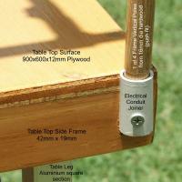
- Top work surface 900x600x12mm plywood.
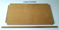
- Lower Full Shelf 900x600x9mm plywood.
- Upper Half-shelf 840x200x6mm plywood (main shelf, not including x2 side suspension pieces).
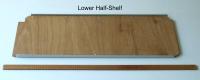
- Lower Half-shelf 890x300x6mm plywood.
- Table top frame cut from 42mm x 19mm pine.
- Assorted sizes of aluminium angle to fit on the edges of the shelves to provide stiffening and prevent objects rolling off.
Legs
- Legs are 25mm square section aluminium tube.
- Leg bottom openings are capped with plastic end caps to keep dirt out of the leg assemblies.
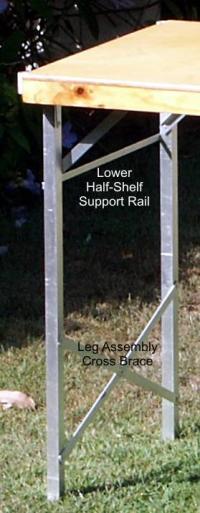
- Leg assembly cross braces are from aluminium bar 25mm x 2.5mm.
- Support rails for lower half-shelf are from aluminium bar 12mm x 2.5mm.
|
 |
|
Click to Enlarge
Fig 3 - Leg Assembly
|
Frame & Flysheet
- Flysheet frame is made from 16mm diameter hardwood dowel, push fit mounted into straight through electrical conduit connectors. (Refer to Fig 5).
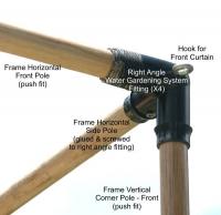
- Frame poles are push fit connected by x4 right angled elbow units from garden watering system components. (Refer to Fig 12).
- Frame cover is a custom made canvas flysheet, to withstand the rigours of the Queensland climate.
Miscellaneous
- Standard card table leg stays are used to lock legs open on the wide leg assembly.
- Home made clip-on leg stays are used to lock legs open on the narrow leg assembly. (Refer to Fig 23).
- School gate hinges fasten the leg assemblies to the underside of the tabletop.
- Assorted plastic clips act as snap-on and snap-off fittings for flysheet frame assembly.
- Assorted screws, rivets and glue.
- 4 straight electrical conduit joiners (grey coloured, 16mm ID) to hold vertical corner poles.
- Length of orange electrical conduit for upper half-shelf fitting.
- Piano hinges for upper half-shelf.
- Carry handle.
- Outdoor gloss varnish finish.
TOOLS
Hand saw, power dill, screwdriver, blind rivet gun.
TABLE TOP ASSEMBLY
Refer to Fig 4 and other photographs for overview.
|
 |
|
Click to Enlarge
Fig 4 - Table Top Assembly
|
Table Top FrameCut tabletop frame from 42mmx19mm timber with 45-degree mitres. Glue, screw and assemble using mitre clamp to ensure squareness. This frame will support the tabletop and house the folded leg assemblies and poles, etc.
Top
- Drill and countersink fixing holes in table top. Screw and glue table top to frame. Sand top smooth and round off all the edges and corners.
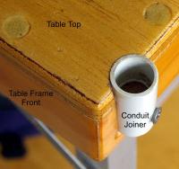
- Take the 4 straight electrical conduit joiners, and insert a tight fitting, short length of dowel into the bottom half of each joiner. This strengthens the joiner when we later drill a fixing hole. Next, clamp small pieces of scrap wood to each corner of the table where the 4 joiners will be located. Drill a 19mm diameter hole vertically into the scrap wood/table top assembly so that when the scrap wood is removed, you leave a semi-circular slot into which the conduit joiner can be snugly located. (Refer to Figs 5 & 20).
- Drill a hole in the lower segment of each joiner, through where the dowel is inserted. Screw each joiner to the tabletop at the corners. These 4 joiners will now hold the x4 vertical corner poles for the flysheet frame. (Refer to Figs 5 & 20 for details).
|
 |
|
Click to Enlarge
Fig 5 - Corner Pole Joiner
|
Leg AssembliesThere are 2 leg assemblies, one wider than the other. The narrow leg assembly folds neatly into the wide leg assembly when closed. Each leg assembly is cross-braced on the inside face with aluminium flat bar for rigidity and has an additional upper rail to support the lower half-shelf. Refer to Fig 3 and other photographs for an overview, before you start cutting material.
Leg assemblies - building
- Cut aluminium legs to size so the leg assemblies do not foul the tabletop frame when they are opened and closed. My legs are 840mm long.
- Cut to size two lengths of flat 25mm x 3mm aluminium bar for cross bracing the wide leg assembly. My wide cross braces are 60cm long for the wide leg assembly.
- Make sure the cross braces are fitted to the inside of the leg assembles to allow for flush closing and for fitting of flysheet frame poles inside the tabletop frame.
- Drill holes for rivets in the cross braces and legs.
- Rivet cross braces to legs, adding a rivet at the crossover point as well.
- Repeat using shorter lengths (56cm) of aluminium flat as cross braces for the narrow leg assembly.
- Cut to size two lengths of flat 12mm x 3mm aluminium bar (x1 wide & x1 narrow) for the lower half-shelf support. Drill holes and rivet narrow bar to outside of narrow leg assembly, wide bar to inside of wide leg assembly to allow for stowing the leg assemblies.
Leg assemblies - fitting
- Drill holes in aluminium legs to accept rivets for fastening school gate hinges to each leg. A school gate hinge has long, parallel sided hinge flaps that fit the 25mm square legs nicely.
- Allowing for leg stay clearance between the frame and wider leg assembly, screw the school gate hinges to the underside of the tabletop.
- Leave sufficient clearance so that the leg assembly may be opened and closed without binding.
- Locate the narrower second leg assembly inside the first one and screw school gate hinges to underside of table top ensuring that the second leg assembly can open and close without fouling the first leg assembly.
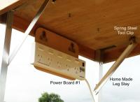
- I fabricated a set of home made leg stays from aluminium angle to lock the narrow leg assembly in place when deployed. Note that these are held in place by tool clips, so these braces can be unclipped and swung out of the way to allow the wide leg assembly fold down inside the table top frame. (Refer to Fig 23).
Storage ShelvesThere are 3 shelves in total; the lower full shelf and the upper and lower half-shelves. Later on, I also added additional storage in the form of a removable wooden shelf unit that my eyepiece box sits on. (Refer Fig 14).
Lower full shelf
Cut lower full shelf to size so it can be slotted between the leg assemblies. I used a 900mm x 600mm x 9mm plywood sheet with cut-aways in the corner. These allow the self to be slotted between the leg assemblies, supported by the cross braces. Note that one pair of cut-aways are deeper to allow for the narrow leg assembly to fit in-between them. I reinforced this shelf with pieces of right angle aluminium edging strip. This prevents shelf droop and minimises the risk of objects rolling off the shelf.
|
 |
|
Click to Enlarge
Fig 6 - Lower Full Shelf
|
Lower half-shelf
This is a simple 890x300x6mm piece of plywood cut to shape. I fitted aluminium angle as edging strips on the long sides to stiffen the shelf and prevent objects from sliding off.
|
 |
|
Click to Enlarge
Fig 7 - Lower Half-Shelf
|
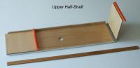
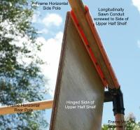
Upper half-shelf
This is a simple 840x200x6mm piece of plywood cut to shape, with two fold down sides (your own measurements) which clip over the upper frame. The fold down sides are fitted to the main half-shelf with piano hinges. These sides clip to the frame dowel using longitudinally cut strips of orange electrical conduit. Again, I fitted aluminium angle as edging strips on the long sides to stiffen the shelf and prevent objects from sliding off.
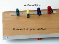
I fitted a short length of aluminium bar and 4 Velcro straps underneath the upper half-shelf to act as a cable tidy.
|
 | |  |
Click to Enlarge
Fig 8 - Upper Half-Shelf
|
|
Click to Enlarge
Fig 9 - Upper Half-Shelf Fitting
|
|
 | | |
Click to Enlarge
Fig 10 - upper Half-Shelf Cable Tidy
|
| |
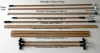
Flysheet FrameThis is made from 16mm and 12mm diameter hardwood dowel. Fig 11 shows the inventory of frame poles. The ends of the poles were slightly reduced to allow for coatings of varnish. This prevents any binding when inserting/removing the poles during assembly/breakdown.
|
 |
|
Click to Enlarge
Fig 11 - Wooden Frame Poles
|
- 16mm x 750mm hardwood dowel for the x4 off Vertical Corner poles.
- 16mm x 560mm hardwood dowel with glued & screwed right angle elbow connectors for the x2 off Horizontal Side Poles.
|
 |
|
Click to Enlarge
Fig 12 - Right Angle Fitting
|
- 16mm x 900 mm hardwood dowel for the Front and Rear Horizontal Poles that connect to the Horizontal Side Poles assemblies. These push fit into the right angle elbow connectors.
- 16mm x 900mm hardwood dowel x 1 off for the central Flysheet Top Support Pole that extends the flysheet over the front edge of the working top to provide additional dew protection.
- 12mm x 900mm hardwood dowel x 2 off for the two lateral Flysheet Top Support Poles that extend the flysheet over the front edge of the working top to provide additional dew protection.
- 12mm x 730mm hardwood dowel for the Rear Central Vertical Pole at the back of the hutch, to prevent the back of the flysheet from blowing in when windy.
I slightly reduced the diameter of the ends of the hardwood poles where they push fit into the plastic components, to allow for the thickness of varnish and prevent potential binding due to any expansion caused by heat and/or humidity.
FLYSHEET
I had an outdoor camping and equipment supply shop fabricate a canvas flysheet for $100. This flysheet protects the top, back and 2 sides of the worktop and storage shelves, overhanging the worktop to provide additional dew protection for the open front access area. Don’t forget to specify any sewn on tape loops for fastening points that you may require.
ILLUMINATION
Large, diffuse area of red light illumination required. Mains powered. Use a small, red-filtered fluoro light to provide a cool, large area of illumination. I used cut offs from theatre grade, red gel filters, fitted inside the frosted tube cover.
ELECTRICAL
I fitted two ELCB protected 5-socket power outlets under the table. This allows me to run a mains power cord to the table, providing 9 local sockets for powering my telescope, notebook computer, PDA, dew heaters, various cameras (ST7, Pentax *ist DS, Orion Star Shoot, etc.), Firewire hub, flat field illumination box, red filtered fluoro light, etc. Please be extremely careful when planning field based electrical requirements. 240V power cables criss-crossing the observing field on a damp night, with people walking around, are lethal if something goes wrong. Seek the advice of a competent electrician.
AfterthoughtsAfter building and using the hutch for a short while, I added the following enhancements.
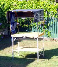
Dew insulation
I purchased some closed-cell 3mm foam mat to fit on top of the frame, underneath the flysheet. This minimises dew from condensing on the under-surface of the flysheet, which may then drip onto the work area, especially if a gust of wind flaps the flysheet. Refer to Fig 13 to see how I shaped this to extend down over the back and sides of the frame.
|
 |
|
Click to Enlarge
Fig 13 - Dew Mat Cover
|
Cable access port
To manage the cables running between the hutch and the mount, I cut a small port hole in the side of the flysheet and covered it with a flap to prevent the ingress of rain. Having a single cable route, along which all the cables run, greatly reduces the chance of tripping on a wayward cable in the early hours of the morning when concentration and alertness are at low ebb. Refer to Fig 18, the last row of photos to see the brown flap on the RHS of the flysheet that covers the cable access port.
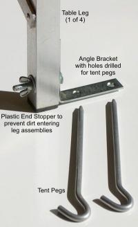
Peg down angle brackets
To prevent the hutch from being blown over (yet again!) in strong gusty winds, I drilled holes towards the bottom of each of the 4 legs where I fit x4 off 3 inch angle brackets which can be pegged into the ground. This seemed a better solution that fitting guy ropes, which no doubt would be a tripping hazard in the dark, especially at astro-camps. Refer to Fig 22 for details.
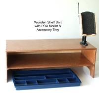
Removable wooden shelf unit
To provide yet more storage! This was built from off cuts of 9mm plywood and was simply glued and screwed. It carries the PDA holder along with my eyepiece box which sits on the top surface. The middle shelf is useful for storing stuff you need to hand, such as webcams, etc. The lower space houses an office drawer organiser that can be slid in and out for storing bits and pieces, preventing them from rolling around the table top.
|
 |
|
Click to Enlarge
Fig 14 - Wooden Shelf Unit
|
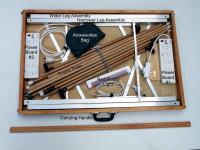
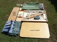
Field AssemblyStowed and exploded views of the hutch prior to its erection are shown in Figures 15 & 16 respectively.
|
 | |  |
Click to Enlarge
Fig 15 - Stowed Hutch
|
|
Click to Enlarge
Fig 16 - Exploded Hutch
|
I can usually set up the hutch in about 5 minutes, as follows:
- Carry the stowed assembly to your chosen location.
- Lay the unit down, table top to grass and unfasten the luggage strap that holds the stowed assembly together when flat.
- Remove the lower full shelf, half-shelves, flysheet, foam mat, curtain, storage pockets, poles, power board and other components from the frame.
- Deploy the leg assemblies and stand the table upright.
- Slide in the lower full shelf at an angle and then locate it in position so that it is supported on the cross braces.
- Slide in the lower half-shelf.
- Clip on the power boards (#1 & #2). (Refer to Figs 19 & 23 for their location)
- Insert 4 Vertical Corner Poles into 4 corner joiner receptacles.
- Fit Horizontal Side Poles to Vertical Corner Poles via right angle elbow connectors.
- Fit Front & Rear Horizontal Frame Poles.
- Fit the middle fluoro Light Support Pole.
- Clip on the fluoro light.
- Clip on the upper half-shelf.
- Fasten the 3 row x 4 pocket accessory holder with Velcro straps.
- Insert Rear Central Vertical Pole.
- Snap on the 3 Flysheet Top Support Poles with end protectors.
- Fit the 3mm foam insulation mat on top of the frame assembly.
- Gracefully and elegantly drape the flysheet over the frame / table assembly and secure it to the frame using the elasticated loops.
- Fit the 4 peg down angle bars, one to each leg and insert tent pegs to hold hutch down in case of strong winds.
- Clip on the front (shower) curtain.
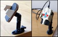
- Fit the removable wooden shelf unit, PDA holder and Tak handset holder.
- Fill with astro goodies.
- Enjoy.
MiscellaneousGeneral notes
- All dimensions are approximate and given in mm.
- Measure twice, cut once.
- Pay attention to which side of the wide and narrow leg assemblies you fit the cross braces and lower half-shelf supports. Riveting the braces or supports on the wrong side will prevent the leg assemblies from folding flat when stowed.
- The Accessories Bag as shown in Fig 15 contains the x4 angle brackets and pegs for securing the hutch, along with various cords, bungies and other small components that travel with the hutch.
Suggested improvements
Here are some improvements I would make next time around:
- Design a sloping roof to spill off any rain water.
Additional Photos
Here are some other general photos of the hutch and components to assist with the design and build process.
|
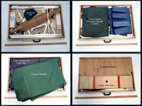 | |  |
Click to Enlarge
Fig 17 - Stowed Mosaic
|
|
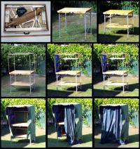
Click to Enlarge
Fig 18 - Assembly Mosaic
|
|
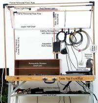 | |  |
Click to Enlarge
Fig 19 - Frame Assembly
|
|
Click to Enlarge
Fig 20 - Joiner for corner poles
|
|
 | |  |
Click to Enlarge
Fig 21 - Tak Controller Mount
|
|
Click to Enlarge
Fig 22 - Leg Peg Bracket
|
|
 | | |
Click to Enlarge
Fig 23 - Power Board & Leg Stay
|
| |
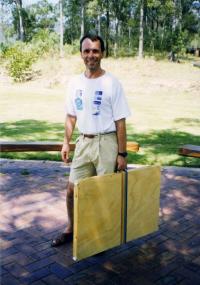
And last but not least, the author and the hutch!
|
 |
|
Click to Enlarge
The Author and the Hutch!
|
Article by Dennis Simmons (Dennis). Discuss this article on the IceInSpace Forum.
|
|
|


