ICEINSPACE

|
Build a Dew Heater from Resistors
Submitted: Thursday, 4th May 2006 by Alan Sheehan B.E
There are many excellent commercially made dew heaters available on the market, but for those with a limited budget, building your own dew heater can be an interesting little project that can save you some money… or perhaps you just like to be able to say you made it yourself! There are many similar web pages describing projects just like this. It’s a good idea to browse these and mix and match techniques to suit yourself. There are different ways to build resistor based dew heaters with switch resistor banks, etc but this project is for a single resistor bank suitable for use with the Pulse Width Modulated Dew Heater Controller project also in the IIS DIY pages. The concept is to build a heater with a number of resistors equally distributed around the circumference of the lens or eyepiece that we want to heat in order to prevent dew formation. As current, assumed from a 12V supply, passes through the resistors, heat is created in the resistors which heats the lens. The resistors will be wired up in parallel, so each resistor will have the full 12 V applied to it. What you will need
Designing Your HeaterFor those who want to understand how to design a dew heater, read on. If you just want to get on with it, there is an Excel spreadsheet to do the calculations for you here (see bottom of article to download it) – just skip down to the Using the Design Spreadsheet section. The number of resistors will depend on the power required, which of course depends on the size of the lens to be heated. A little reverse engineering applied to the commercial dew heater data available on the web produces the following equation for the power required for various sized lenses:
Where P = power in Watts So, for example, an 80mm lens requires 0.0606 x 80 + 1.18 = 6 Watts.
Where P = Power in Watts So, for example, assuming we use a 12V supply, the heater for our 80mm lens will draw: I = P / V = 6W / 12V = 0.5 Amps. Now the total resistance of the heater can be calculated from
Where V = Volts So, R = V / I = 12V / 0.5 A = 24 Ohms. This is the total resistance of the finished heater. A single 24 ohm resistor would produce the required heat but it would be all at one spot on the edge of the lens, which is not what we want. We want several resistors equally spaces around the circumference. For resistors in parallel
where R = total resistance in ohms For R1 = R2 = R3 =…:
where R = total resistance in ohms Resistors are commonly manufactured in 1/4W, 0.5W and 1W power ratings. We need to ensure we don’t use a resistor with too few ohms for it’s power rating (or it will burn out), so by combining Eq.3 and Eq. 2:
Rearranging Eq. 6 gives: Rmin = V2 / P So, for a 12V supply and: I chose to go with 0.5W resistors as a compromise between the number of resistors and the spacing between them. Choosing a common resistor size with a value greater than 288 ohms, I selected a 390 ohm metal resistor rated at 0.6W (0.5W were no longer available from my supplier). So once an appropriate resistor size is chosen, Eq. 5 is used to calculate the total number of resistors required. For our example 80mm diameter lens:
To work out the spacing of the resistors, measure the actual outside diameter of the lens and add 2mm (for the diameter of the resistors) and multiply the whole thing by pi. Say, for our 80mm lens example the actual outside diameter is 90mm, then the pitch circle diameter of the resistors is 90mm + 2mm = 92mm, which has a circumference of 92 x pi = 289mm. So the spacing, of the resistors is 289mm / 16 resistors = 18mm per resistor. This equation can be written:
Where Doutside = Outside diameter of the lens in mm The Excel spreadsheet here can do all these design calculations for you. Download the Design Spreadsheet
Using the Design Spreadsheet
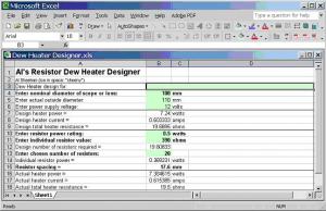
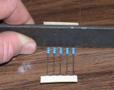
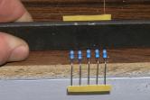
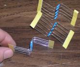
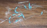
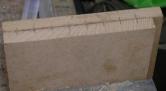
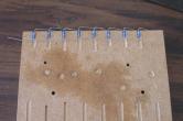
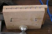
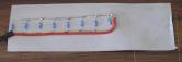
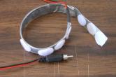
Al’s Resistor Dew Heater Designer is a Microsoft Excel spreadsheet for performing the above described calculations. It should look like this when you first load it. The cells shaded light green are the ones you need to enter data into. In cell B3, enter the name or description of the lens you are designing the heater for. Next, enter the nominal size of the lens in cell B4. This is used to calculate the power needed for the heater. Now you need to take a measurement of the outside diameter of the lens. The lens cell, which supports the elements of the lens, will mean the outside diameter is larger than the nominal (or clear) diameter of the lens. Callipers are best for taking this measurement, but often an accurate enough measurement can be made with a simple ruler across the end of the lens/OTA/Eyepiece, so don’t worry it you don’t have any callipers. Enter this measurement into cell D5. This is used to calculate the circumference of your heater, and so also the spacing between the resistors. In cell B6 you can enter the applied voltage for your heater. The default is 12V, but if you want to design one for a different voltage you can. Now you need to decide on what value and power rating resistors you plan to use. I played around a bit with different power ratings before settling on 0.5 watt resistors. I found that 0.25 watt resistors meant I had to use a lot of resistors and they were very close together. Great for even heat distribution, but probably more expensive in resistors, but more importantly, tedious to build. On the other hand, 1 watt resistors tended to be too far apart for smaller aperture heaters like eyepieces, etc. Maybe, I am conservative, but just 3 resistors around an eyepiece may be starting to introduce uneven heat distribution which could affect the optical performance of the eyepiece. Maybe… So I compromised and went with 0.5W resistors. To make optimum use of your resistors, you want to use the smallest resistance value possible without exceeding the resistor’s power rating. Play around with values in cells and you will see that warning messages appear if the power rating of the resistor is exceeded. Try to stay with standard resistor values. I found that at Dick Smith Electronics, 0.5W resistors were pretty rare these days – they seem to be replaced by 0.6W resistors. So even though I designed for 0.5W, using 0.6W resistors just added some fat to the design. I could have reworked the design and gone for 0.6W 330 ohm resistors but 0.6W 390 ohm would do. Having selected your resistor value, there is just one final decision – how many resistors. Cell B12 is the theoretical number of resistors required for the heater, but you will find this is probably not a whole number… so round it up to down to the next whole resistor as you see fit. And there you have it… your design is done! All you have to do now is build it. Building the HeaterOne of the good things about using 0.6W, 0.5W or 0.25W resistors is that the spacing of the resistors is close enough to allow you to solder the resistors together using just the wire tails on the resistors. 1W resistors will probably be spaced far enough apart to need a piece of hook up wire between each resistor! I decided to try to “mass produce” my dew heater so that things were consistent, hoping that that would help it to look better. As my resistors came in sets of five I started by bending them into Z shapes ready for soldering. Figure 1 shows the use of a piece of flat bar to bend the tails of the resistors up square. A wooden ruler would do just as well for this job. Figure 2 shows the bent legs of the resistors over the edge of the bench while the other end was bent to opposite way. Figure 3 shows the groups of 5 resistors bent into the Z shapes – ready for soldering once the tape is stripped off the wires – as is shown in figure 4. To get the spacing between the resistors consistent while soldering, I made a little jig from 2 scrap pieces of MDF. Any scrap timber should do. With the scrap timber clamped together in a vice as shown in figure 5, mark and drill holes down through the “join” between the two pieces of wood. I used a metal drill so I drilled until the flutes of the drill clogged and that was more than deep enough. A 3mm or 1/8” drill should do the job. Finish the jig off with two holes straight through both pieces of wood before you take it out of the vice. These holes will allow nails to be used as alignment guides for the jig. Figure 6 shows the resistors laid out in the jig. Align the end of the body of the resistor with the top edge of the jig to try to keep them straight as well as evenly spaced. When the jig is assembled with the resistors in place ready to solder, it should look something like figure 7. Note the nails used as alignment guides. A G clamp was also used to clamp the jig together and keep it standing upright while the resistors are soldered. After, when all the resistors are soldered together, attach the power leads as shown in figure 8. Note the resistors are laying on a piece of duct tape (sticky side up). This was my chosen method of covering for my heaters. If you are a sewer… hmmm… one who sews ;o) you could make a much more professional cover from fabric. Fold the duct tape over the resistors from both sides. The result should be one layer of duct tape on one side of the resistors and two on the other. The side with just one layer, will be the inside, or the side that contacts the lens or OTA, since we want to maximise heat transfer to the lens. Notice also that the duct tape is a few inches longer than the resistors. This is the overlap to allow some adjustment in diameter and also for fastening of the heater. In keeping with my no-sew solution to making dew heaters, I used Velcro dots to provide the final attachment method. Again if you are one who sews, you could sew in strip Velcro and make a more professional looking job of it. Figure 9 shows the finished heater. Once it has been rolled to shape around the lens or eyepiece I recommend you minimise flexure of the heater to avoid fatiguing the wire joining the resistors. Loosening it to remove and replace it is OK, but try to keep it in its circular shape about the right size, and you will have no problems with broken wires. You can now enjoy dew free observing thanks to dew heaters that you not only built yourself, but designed yourself, and should only cost a few dollars to make!
 |
|
|||||||||||||||||||||||||||||||||||||||||||||||||||||||||||||||||