ICEINSPACE

|
Digital Imaging - Flats and Darks Explained!
Submitted: Sunday, 19th June 2005 by Eddie Trimarchi
IntroductionBasically, Flats and Darks are special-purpose images taken under specific conditions in order to calibrate digital images taken under similar conditions. Not all imaging systems may require them, but hopefully by the end of this article you will be able to decide whether yours does or not and whether you want to go to all the trouble of dealing with them. Darks
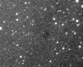
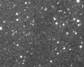
Digital images are a brightness map converted from a charge accumulated in pixels on a CCD chip. Pixels in a CCD chip can generate a charge for several reasons but here we are mainly concerned with the two effects; i) photons hitting the pixel (i.e. light) and ii) a charge accumulated by heat. Heat is a problem and causes a charge to build in a pixel in the same way that light does. This is called Thermal Noise. Darks are characterised by a peppery look as seen in the image on the right. The bright pixels are thermal noise and the brightest ones can cause vertical lines as they leave a residual charge behind when the rows are moved down during readout. Caused directly by hot pixels, these lines will also be in your images and will be calibrated-out after dark subtraction. The longer the exposure and the warmer the chip, the more thermal noise there will be and this is why most astronomical digital cameras are cooled. Thermal noise is a known quantity and builds up more-or-less constantly over time at a given temperature. This means that if we take an image in total darkness at the same temperature and for the same duration as the rest of our images, we can simply subtract it and remove the thermal noise. This image is called a Dark Frame or sometimes simply, a Dark. In order to remove thermal noise effectively, we need to be able to control the temperature of the CCD chip and this is why many cameras have regulated cooling, so that specific operating temperatures can be maintained or duplicated in order to create accurate Darks. Master Darks There are random effects in darks that can cause pixels to not accurately reflect thermal noise, so it is often beneficial to create a Master Dark by median combining many darks taken at the same exposure time and temperature. The median combination will tend to reject any extremely different pixel values between darks and creates a more accurate map of the thermal noise. Dark Use Not all digital cameras/images require dark subtraction. The latest CCD chips feature very low thermal noise characteristics, but typically will still have some at a very low brightness level. Whether you see it or not depends on many things, not the least of which is the brightness of the target object. If it is very bright, and your cameras thermal noise is low then the thermal noise will likely not be seen as it swamped by signal from the object, but if the object is dim then parts of it will probably be around the same brightness as the noise. If you want these parts of the object to be clearly visible then you will need to subtract a dark to remove the noise portion from it, leaving only the low-level signal from the object. Typically, I will use from 6 to 10 darks to create a Master Dark that I will use for several months, perhaps an entire season depending on the stability of the climate. For instance in early winter, it is possible for me to get my camera down to about 14 degrees Celsius while maintaining a cooling buffer of 20%, meaning that the cameras cooler is working at around 80% efficiency. This allows for temperature variances during the night. If the temperature rises, the cooler will be able to keep up with it and maintain a constant chip temperature of -14C. A 20% buffer equates to only a few degrees, so it is important to ensure that a buffer is maintained. By ensuring that the cooling temperature is maintained and also that your sub-images are all the same duration, Master Darks can be used indefinitely. For situations like different seasons, objects of different brightness/exposure requirements, etc. a library of master darks can be accumulated over time for future use or created during those nights unsuitable for imaging. For cameras that do not feature regulated cooling, but do need thermal noise reduction it is best to take darks on the same night as the images they will be calibrating to ensure that the temperature is as close as possible to when the images were taken. Consumer digital cameras generally include their own internal libraries of darks and so should not need dark subtraction as they are applied automatically whenever an image is taken. But in the dark old days, thermal noise was dealt with by simply not giving it time to build up to significant levels. Hence older digital cameras were only capable of very short exposures and in the absence of signal (i.e.darkness) were very noisy, as whatever light was there was at or below the noise levels.
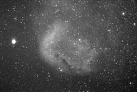
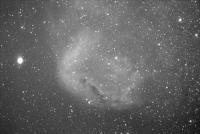
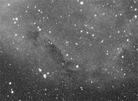
A Dark ExampleThe difference cannot easily be seen in this example because of the image size reduction though the resulting image does look smoother. But the real difference is seen at full size. Here is a zoom-in of a small area in both images to highlight the difference.
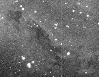
Note that both of these images have been significantly stretched to show the low-level thermal noise. Youll want to get as much of the objects signal as possible to dominate the information in the image. Removing as much thermal noise as possible will allow you to take your images deeper than you could otherwise. Note that even though the difference doesnt look like much in this example, if you are to be adding images together, the noise will also build up. Here is an example showing six images added together both with and without darks subtracted.
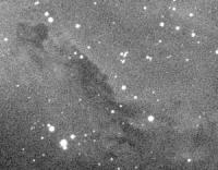
The difference becomes much more noticeable as more images are added and can become even noisier if the images are slightly misaligned as the noise tends to be in the same place in each image, when the images are aligned the noise is shifted with respect to other images. Sp adding the images together will then distribute the noise over a wider area. From the examples above, you can see that a single ten-minute image thats been dark subtracted looks about as noisy as six raw ten-minute images summed. But the summed result of six dark-subtracted raw images speaks for itself! Do you need to worry about it? Even if you think your images dont need it, do a test one night to confirm it. Take a single dark frame and subtract it from one or more of your raw images then stretch both the original raw image and the dark-subtracted version as much as possible. If you can see a difference, then it is beneficial. Especially if you plan to add images together. The less noise there is in each of the images being added, the better the result will be. If you decide that you want to make dark subtraction part of your standard operating procedure, then make it the first step in your image processing routine. If you dont have temperature control on your camera, try and bracket your darks around the images they will be used for by simply shutting off the light to your camera and taking equal-length exposures. Between 5 and 20 should do for a good master dark. Flats - The Next Step
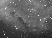
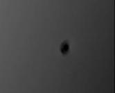
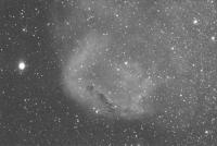
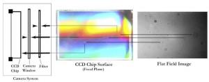
Flat fields are used to compensate for any uneven illumination in images that are caused by the optical system. One of the most common things encountered by astrophotographers is vignetting. This is where the image has captured a wider field than is clearly available to it. The effect is usually seen in images as a bright central area with darkened corners. Another thing commonly blocking your view is dust or other particles on the optical surfaces near to the focal plane. Typically an image may record the out of focus images of all particles between the primary (objective lens or mirror) and the focal plane (ccd chip or film), though realistically only the closest elements to the focal plane are of any real concern. Like the ccd surface, camera window, filters, eyepieces, barlows, etc. Particles closer to the focal plane will appear in images as more in-focus than those further away. In any case, what we are seeing is disruptions to the target object field by influences in the optical path. They can easily be seen in the image to the right and can be easily dealt with by flat fielding. Creating a Flat How do you create a flat field? By taking an image of an evenly illuminated light source across the entire telescope aperture and with the telescope at the same focus and orientation to the camera, as the images they will be calibrating. Unlike Darks, the temperature and exposure times are not relevant. The main aim is to get a flat field that has an average pixel value of about 30% of the maximum pixel value that your camera is capable of. For a 16-bit camera, this would be approximately 20,000. Most image processing software will give you the average pixel value in an image so this value is generally easily obtained. Flat fields should also be dark-subtracted, and as with standard darks, a master dark for your flats will be better than a single dark. Its all a matter of how much time and effort you are willing to spend. In a pinch, a single flat with a single dark subtracted from it, can be much better than none at all. The resulting flat field image is an obstruction map for your optical system that is then applied to your images, to remove the obstructions from them. Applying Flats to Images Flats are applied by numerical pixel division into your images. But its not a simple division, the flat must be normalised to 1.0 for each of the images so that its brightness is relative to the image being calibrated. Most image processing software includes a flat field process that applies the flat correctly to images. Otherwise you would need to normalise the flat and divide it into the images yourself, essentially performing a manual flat field. But software that allows image arithmetic will likely also have a specific flat field function, so this shouldnt be necessary. Master Flats As with Darks, Flats may contain individual irregularities that can be minimised by an average or median combination of multiple dark-subtracted Flats. The average or median combination will minimise these effects to create a more accurate Master Flat. If you do median combine flats to make a master flat, then (unlike when creating a master dark), you should normalise them by selecting one as the master and normalising the rest of the flats to it prior to combining them. This is to ensure that all of the component flats are of equal central brightness prior to combining them. Again. Median combination is best done by software capable of combining with normalisation as an option, otherwise an average combination will do if you dont want to manually normalise them. Different Types of Flats There are several common ways of taking flats. So-called T-Shirt flats are probably the easiest to do and are taken by laying a T-shirt or other diffusing material across the front of the scope. Images are taken of the sky or other bright, flat evenly illuminated surface adjusting the exposure time to give the optimal 30% average pixel value. The material serves to diffuse and dim the incoming light and ideally should not have seams or folds and should be of equal thickness across the aperture. You could just use one of the shirts from your wardrobe, or you could devise a special-purpose device with material stretched over a ring custom-fitted to your scope. Twilight flats are just like a T-shirt flats but without the T-Shirt and taken on the dark side of either dusk or dawn. As a rule of thumb, the darkness needs to be just right for a 5-second image to not saturate and give you your 30% average pixel value. This is a little more difficult due to the sky brightness changing by 50% every 60 seconds. So once started, you only have about 3 minutes to take your flats before it will be either too dark or too light, depending on whether youre shooting at dusk or dawn. This method is further complicated if you need flats taken through multiple filters (e.g. RGB flats) as the required exposure times will be different for each filter and you will have to carefully plan the filter sequence, exposure times and number of flats you can take in the time that you have available as the world turns beneath you. The resulting images will need to be normalised to achieve a common central brightness, compensating for the changing sky brightness. Also, the telescope should not be tracking during exposures in order for any stars in the image to trail. The trails will later be removed by median combination. A Light Box is my chosen method of acquiring flat fields and allows the process to be controlled and therefore standardised. Basically the box provides the illuminated flat surface using light bulbs in a box and a light diffuser. This is then placed on the end of the scope for taking flats. A light box can easily be made from cheaply obtainable parts. Ive included a quick and dirty light box design at the end of this article. Practical Flat Use A flat can be used indefinitely as long as the camera-to-lens orientation and focus have not changed and nothing has been introduced into the optical system. Adding filters, lenses, a lens shade, rotating the camera on the telescope, etc, would all require flats to be retaken to use with new images. Normally, you would use a different set of flats for each configuration. If you remove the camera often, registration marks can be used to help you realign it consistently so that flats can be reused. Hopefully, no new dust particles will have been introduced but if anything significant shows up in your images, then flats may need to be retaken. Flat Example Here is an example showing an area of the image that has both a dust donut and a brightness drop-off due to vignetting.
The resulting image is much better with the darker corners gone and the background looking much flatter and more natural. Of course, this is not the finished product but only a single 10-minute image. The process must be applied to all of the raw frames before they are combined. But you would not do them one at a time. All image processing software should allow you to process your images in batches, otherwise it might all be considered too much trouble! So where is all this dust?
When realising that grimy optics is a problem, your first thought would probably be, “No problem, I’ll just keep everything clean!” Although this is a good tactic, you will soon discover that it is virtually impossible to achieve! Particles that look large in images are generally tiny, and may not even be visible to less than a very careful inspection, let alone obvious enough to clean. Even if you do clean well, the chances are that by the time you put everything back together, more dust has appeared magically from somewhere. It’s not uncommon to think you have removed every speck, only to find later that your Flats appear not much different to before. At this point, you would probably not be alone in realising that it’s much easier to just do flats than to have a spotless optical system. In my system, I have five surfaces that typically show up spotty in flats, most of the dust donuts will be one of three sizes and this gives away their location. For a more accurate method of determining the location of dust motes, the distance of particles from the focal plane can be calculated directly from the Flat in millimetres with the formula: d = (p * f * d) / 1000 Where: d = the distance in mm from the focal plane to the dust, p = pixel size in microns, f = the f value of the system (or focal ratio) and d = the diameter of the dust spot in pixels. Although once familiar with your system you can locate specks fairly easily by the size of the mote in the Flat, this calculation can help you home in on troublesome spots and become familiar with your setup. ConclusionThats about it for a rough and ready overview of darks, flats and general image calibration. Many details have been glossed-over as this topic could easily constitute a short course, but this article was intended to highlight the effects in raw images that calibration is intended to correct and introduce the functional requirements for performing these calibrations. For a more detailed coverage of image calibration or imaging in general, I would recommend either of the excellent books mentioned in the References section at the end of this article. Appendix A - Building a Simple Light Box
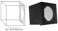
Here is a simple design that I have made and have been using for several years. It is by no means the best design, but entirely adequate to the task. The box is made from 4mm white foam core board of the type used by picture framers as backing for prints, etc. This is light, white, can be easily cut to size with a craft knife and glued together solidly with epoxy or even taped together with cloth or other durable opaque tape. Off-cuts of the foam core can be used to make the four baffles seen in the diagram as a small panel next to each light bulb. The purpose of these is to shield the diffuser from any direct light from the bulbs. They should not be high enough to block the light from the bulb reaching the rear corner of the box furthest from the bulb. This ensures the most uniform illumination of the rear surface of the box, which is where the diffuser will get all of its light from. The diffuser is translucent white “milk plastic” of the type used by sign writers, is available from suppliers to the sign industry and shouldn’t be difficult to find. The bulbs should burn as white as possible. The box will be used to make flats for filtered images as well as unfiltered and some standard bulbs tend to emit light toward the red end of the spectrum. When you combine this with the relatively lower blue response of CCD chips, you may find that you require a 1 second exposure through the red filter and 200 seconds through the blue at the same bulb brightness. This was the case with standard 12vdc torch bulbs I tried initially. I’ve now moved to 25W Ultra White halogen bulbs, but 10W would probably do for smaller than a 12” box like the one shown. Dimensions: The box can be any size you want. The goal is even internal illumination so a cube will do nicely, made slightly larger than the maximum diameter scope you want to be able to use it on. The picture above shows a 12” box, but I have used it for many apertures down to as small as 2”. Wiring: The example above is 12vdc and the bulbs are wired in series. You can make modifications such adding an on/off switch or a 12vdc dimmer for more flexibility. Operation: For the light box to work properly all four bulbs should be of the same type and naturally all four bulbs need to be working. In my box, I placed an LED in the wall of the box next to each of the bulbs. This makes it easy to check that each bulb is working. The LED doesn’t need to be powered, as the light from the bulb will simply shine through it, so even blown LEDs are well suited for this purpose. To use this box, I point my telescope straight up and rest the box, with the diffuser pointing down, directly onto the end of the telescope. After the flats have been taken, you can turn the lights off and take your flat-darks. That’s it! This is a quick and dirty generic example of how a light box can be constructed. You will probably find yourself incorporating your own design features into the box as you search for materials and begin construction. Light box construction can be a science in itself from the internal dimensions to the type, brightness and spectral output of the bulbs used, but hopefully this brief introduction will be enough to get you going. References
Article by Eddie Trimarchi. Discuss this article at the IceInSpace Forums.  |
|
||||||||||||||||||||||||||||||||||||||||||||||||||||||||||||||||||||||||||||||||||||||||||||||||||