|
Setting up a Basic Celestron Wedge
Submitted: Thursday, 12th January 2012 by Peter Coates
 |
 |
Click to Enlarge
Angle Plate Alignment
|
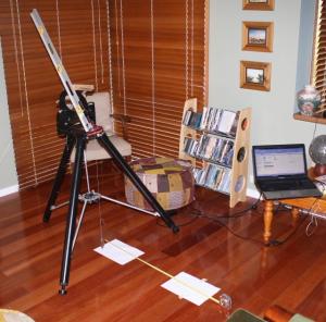
I have been frustrated in the past levelling my C8+ Celestron on its basic as supplied wedge mount. I decided that if I could firmly lock the wedge relative to the base and then always ensure the base was level I would save myself considerable setup time.
It’s all basic stuff but I wanted a repeatable method and one which I could carry out prior to any trip and have the mount set up with the correct altitude for that location.
I could have bought an inclinometer on ebay for about $30, accurate to 0.1 degrees but I was bored, it was cloudy, and I enjoyed the exercise. Plus, I get better accuracy than 0.1 degrees.
I have provided a small excel program that does all the calculations.
The tools required are:
- a floor and wall – preferably perpendicular but any error can be calculated out if necessary
- A good builders level – the bubble levels are useless in my view
- A laser pointer.
- Three sheets of A4 paper
- A tape measure- 2 or 3 metre should do.
- Plumb Bob
- The excel spreadsheet with this document.
Setting up a level base
- Dispose of the nylon washers on the angle plate and replace with large thick flat washers. The nylon washers deform and do not provide repeatable results when locking up the plate.
- Mount stand about three metres from the wall and square up the plate. The further the better as it will show up any mount base levelling errors much easier. On mine my legs are true enough to the plate and I used them to square it up.
- Using the spirit level adjust the legs till the plate is true when the level is placed NS and EW across the top of the plate. The level can sit on the raised sides do not try to level the plate using the lower inside surface which on mine is not all that flat.
- Put the plumb bob on the mount so that it hangs of the front (to you) at the centre. Stick a piece of paper on the floor below it and fix to the floor with masking tape.
- Make a NS EW cross on the paper directly below the plumb bob.
- At this point you could also mark where you legs are, telescope mount legs that is – not yours, in case you kick it later on.
- When satisfied place the laser beam on top of the spirit level pointing NS so that the beam hits the wall. If it’s a good spirit level the top surface and the lower surface will be parallel.
- Stick a piece of paper on the wall with masking tape and mark the laser dot. If the dot is largish make sure you mark the top and bottom of the dot as this may create error.
- Take the measurement a, b, a1, b1, and g and enter in the excel spreadsheet. When measuring b1 remember to include the spirit level and the height of the laser beam above it.
- If a=a1, b = b1, and your measured g = the calculated g, then the mount base is level. Any errors are likely to be in the floor and wall not being perpendicular or a bad reading on the spirit level.
Do not go to the next stage unless you are sure the base is level.
|
 |
Click to Enlarge
Base Plate Leveling
|
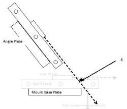
Setting the angle plate
- Place the spirit level on the face of the angle plate and clamp. Make sure it is flat to the plate, pointing NS, and not touching the flat surface of the mount. You do this for two reasons:
- To ensure a flat surface for the laser beam to mount on
- To allow the laser beam to be high enough so that it misses the base plate.
- Attach the laser beam with a masking tape to the level so that the beam intercepts the imaginary NS line between the wall and the mount.
- Place a piece of paper on the floor under the laser dot and fix with masking tape.
- Mark the laser dot at the point closest to the mount. My dot was 4 mm in diameter so I was very careful to always mark the same edge.
- Measure f and b1 + d, in this case d is the difference in the two beam intercept points and would be negative as the beam intercepts lower than the original laser beam, as shown in the diagram here. Pale grey is the setup for the base measurement. It is easy to do this by measuring the vertical height from the floor with the tape and simply noting where the lower edge of the laser beam intercepts the tape.
- Enter these values in the spreadsheet at B10 and B11
- Enter the required altitude in decimal in the cell B16. In my case, Sunbury, my latitude is 37°45’, therefore I require a 52°25’ setting. 25’ = 25/60 degrees or 0.416667, i.e. 52.416667°.
|
 | |  |
Click to Enlarge
Setting the Angle
|
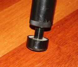
|
Click to Enlarge
Tripod Adjuster
|
How to analyse the results and use the spreadsheet
Your initial efforts will perhaps provide strange results as here it becomes a matter of iteration until you get the closest result. The equations in the spreadsheet are simple and I did not want to go the trouble of differentiation and integration to arrive at the perfect result from a single measurement and single adjustment.
Results Description
- Column B the results based on you measurements – entered in the blue cells
- Column C the minimum total error based on a 1 mm measurement error . Ignore these until you are close to the best result.
- Column D the maximum total error based on a 1 mm measurement error . Ignore these until you are close to the best result.
- Column E this is the ideal result you can expect based on the most recent measurement of the height of the triangle i.e. b1 + d. Because no consideration is given to adjusting b1 + d to allow for the small variation in intercept height produced by a small change in angle we will creep up on it.
Worked Example
Iteration 1
My first attempt gave 861 mm height and 670 base.
| Step 2 Measure Angles |
Measured |
Min Err |
Max Err |
Ideal |
| Laser beam height - b1 + d |
861 |
862 |
860 |
861.000 |
| Base of triangle - f |
670 |
669 |
671 |
658.761 |
| Hypotenuse - e |
1091 |
1091 |
1091 |
1084 |
| |
|
|
|
|
| Results |
|
|
|
|
| Calculated Angle - 0 |
52.11 |
52.18 |
52.04 |
52.58 |
| Complementary Angle - ß |
37.89 |
37.82 |
37.96 |
37.42 |
| Target Angle |
52.58 |
52.58 |
52.58 |
52.58 |
| Error - Deg |
0.47 |
0.40 |
0.55 |
0.00 |
| Error - arcmin |
28.31 |
23.89 |
32.73 |
0.18 |
| Error - arcsec |
1698.49 |
1433.21 |
1963.85 |
10.80 |
This gave an angle of 52.11, a long way out. The ideal based on 861 is 658.7, so I will use 652 and see what happens.
Iteration 2
I marked 652 on the paper and adjusted the plate till my laser dot was on it.
The next set of measurements gave 859 and 652, the height has changed as a result of the angle change.
| Step 2 Measure Angles |
Measured |
Min Err |
Max Err |
Ideal |
| Laser beam height - b1 + d |
859 |
860 |
858 |
859.000 |
| Base of triangle - f |
652 |
651 |
653 |
657.230 |
| Hypotenuse - e |
1078 |
1079 |
1078 |
1082 |
| |
|
|
|
|
| Results |
|
|
|
|
| Calculated Angle - 0 |
52.80 |
52.88 |
52.73 |
52.58 |
| Complementary Angle - ß |
37.20 |
37.12 |
37.27 |
37.42 |
| Target Angle |
52.58 |
52.58 |
52.58 |
52.58 |
| Error - Deg |
-0.22 |
-0.29 |
-0.14 |
0.00 |
| Error - arcmin |
-13.06 |
-17.53 |
-8.59 |
0.18 |
| Error - arcsec |
-783.71 |
-1051.65 |
-515.68 |
10.80 |
Still out but halved the error. My next target is 657 mm.
Iteration 3
I marked 657 on the paper and adjusted the plate till my laser dot was on it.
The next set of measurements gave 860 and 657.
| Step 2 Measure Angles |
Measured |
Min Err |
Max Err |
Ideal |
| Laser beam height - b1 + d |
860 |
861 |
859 |
860.000 |
| Base of triangle - f |
657 |
656 |
658 |
657.995 |
| Hypotenuse - e |
1082 |
1082 |
1082 |
1083 |
| |
|
|
|
|
| Results |
|
|
|
|
| Calculated Angle - 0 |
52.62 |
52.70 |
52.55 |
52.58 |
| Complementary Angle - ß |
37.38 |
37.30 |
37.45 |
37.42 |
| Target Angle |
52.58 |
52.58 |
52.58 |
52.58 |
| Error - Deg |
-0.04 |
-0.11 |
0.04 |
0.00 |
| Error - arcmin |
-2.33 |
-6.78 |
2.12 |
0.18 |
| Error - arcsec |
-139.88 |
-406.99 |
127.32 |
10.80 |
Still out but quartered the error. My next target is 658 mm.
Iteration 4
I marked 658 on the paper and adjusted the plate till my laser dot was on it.
The next set of measurements gave 860 and 658.
| Step 2 Measure Angles |
Measured |
Min Err |
Max Err |
Ideal |
| Laser beam height - b1 + d |
860 |
861 |
859 |
860.000 |
| Base of triangle - f |
658 |
657 |
659 |
657.995 |
| Hypotenuse - e |
1083 |
1083 |
1083 |
1083 |
| |
|
|
|
|
| Results |
|
|
|
|
| Calculated Angle - 0 |
52.58 |
52.65 |
52.51 |
52.58 |
| Complementary Angle - ß |
37.42 |
37.35 |
37.49 |
37.42 |
| Target Angle |
52.58 |
52.58 |
52.58 |
52.58 |
| Error - Deg |
0.00 |
-0.07 |
0.08 |
0.00 |
| Error - arcmin |
0.19 |
-4.26 |
4.64 |
0.18 |
| Error - arcsec |
11.49 |
-255.50 |
278.56 |
10.80 |
Note that this time the adjustment was so small that there was no measurable difference in the height of the laser beam at the plate.
Now look at the margin of errors . The aim of the exercise is to get your measured error below your margin of error. There is no point getting you measured error down to 1 arcsec if the systematic error of the test rig is 200 arcsec.
With your current setup and accepting a 1 mm readability the best you can expect is ± 260 arcsec. The systematic error is so much larger than the measured error there is no point continuing.
Now all you have resolved here is the best possible mount settings. Their still remains an error related to the centre line of the optic and fork assemble and how perpendicular it is to the angle plate. And if you wish to do astro-photography you will still need to have some form of micro adjustment when carrying out drift alignment.
However for those of us with simple setups this should provide at least a repeatable viewing result.
It seems a lot of work but it took me much longer to write this than it did to do the test.
My next project is to investigate the mechanics of changing the bottom two bolt fixings on the angle plate/scope mount to sturdy ball and socket joints with locking mechanisms and the top bolt to a lockable adjustable bolt. This will be my micro altitude adjuster. I am also looking at a balancing and damping mechanism for the fork which currently reacts all the scope and fork mass through the RA bearing assembly.
Article by Peter Coates (rainwatcher). Discuss this article on the IceInSpace Forum.
|


