|
More Illuminated Finder Ideas
Submitted: Thursday, 12th January 2012 by Peter Coates
 |
 |
Click to Enlarge
Red Led Dimmer
|
Following on from an article which had an illuminated finder, here's some more ideas on having an illuminated finder and dimmer.
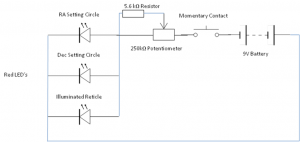
The diagram below shows my set-up, which, as most of your DIY people will tell you is over powered. The LED’s are 1.7 V so a total of 7.3 V has to be dropped over the 100 k pot and the 5.6 k bridging resistor. My logic behind this is the components on my build were what I had on hand and as such I used them.
This circuit could be simplified and optimised by using a two 1.5 V batteries, a 1k Pot and the 5.6 k bridging resistor. The resistance range is then 57 to 0 Ohms. This would give much better range of glow than mine does. 21 Ohms on the Pot is a balanced circuit so be careful not to overdrive the LED’s for too long. If in doubt put a 15 Ohm resistor between the pot output and the wire to the LED’s this will limit the V across the LED’s to about 2 V.
Total current draw is about 60 mA using the high output LED’s, so best to use it momentarily as needed. I could have put them in series to drop the current but then there is no redundancy, although I don’t think I have ever seen a LED burn out of its own accord.
|
 |
Click to Enlarge
Circuit Diagram
|
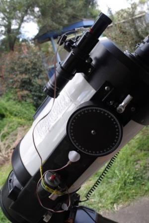
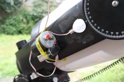
The basic design is as shown below using a film canister as the holder. The 9 V battery is held to the canister with an elastic band and the whole assembly strapped to one of the fork arms with a plastic tie. The LED’s for the setting circles are held in place sandwiched between two Velcro pads. Prior to the Velcro I used a small piece of black card as a cover and some cello tape.
The finder shown in my setup is currently just a trial unit, a cheap 6 x 30, which I did not mind experimenting on. I simply drilled a hole the size of the LED head in the plastic just in front of the cross hairs and pushed the LED in. I painted one side of the LED black so that it could not be seen in the filed of view. This will not be necessary on my final guider eyepiece as I will not be poking it so far in.
In the photo it is shown uncovered but in practice it is hidden under a piece of Velcro strap which I took off my Laptop power supply cable. I could have glued a bezel on to make it prettier but this was only a trial. I am now modifying an eyepiece in the same manner. I have purchased an etched plain lens for this purpose, however the diameter that arrived is 0.2 mm too big so I am having to grind it down, hence no photo of the final item.
I hope someone finds this useful.
|
 | |  |
Click to Enlarge
Dimmer switch
|
|
Click to Enlarge
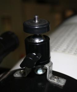
Cheap Piggyback Mount
|
Article by Peter Coates (rainwatcher). Discuss this article on the IceInSpace Forum.
|


