ICEINSPACE

|
Dew Heater Control and the Arduino
Submitted: Monday, 5th July 2010 by Bob Stephens
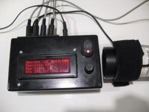
Late last winter I completed a Dew Heater controller based on an Arduino Duemilanove. I included automated Dew Point calculations along with temperature sensing under each heater strap and an LCD display of key data. Some of the detail was published on an associated thread. The controller manages 4 channels, by using an Arduino Mega or other microcontroller many more channels could be controlled if there was a need to do so. The individual heaters start to cycle when the temperature sensors located under the heater straps drops to 5° C above calculated dew point and the duty cycle increases as the temperature gets closer to dew point. Key values are displayed on the LCD screen (which has adjustable backlight brightness).
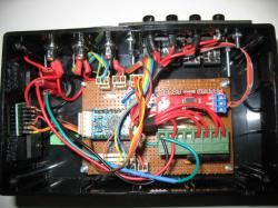
I’ve recently completed two more of a new version using an Arduino Pro Mini trying to reduce the physical size, the component count, the complexity of construction and the cost (I don’t think that I nailed that one). Most recently I’ve finished one based around a PCB design I’d done in the Eagle tool and had made up. A couple of things I’m not happy with in that design but it was much easier to assemble than the veroboard version.
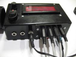
The most recent veroboard version and the PCB design are sized to fit to the mounting holes of a 20x4 LCD display. The PCB boards are being made via Sparkfun’s Batch PCB service. I’ve included 3* 2.1mm power sockets on the unit so that it can be used as a hub to power other items.
A number of my parts were sourced from Sparkfun in the USA, I’ve since discovered that Toys Down Under carry some of the Sparkfun range at good prices. The parts came from a number of sources:
The source code is based on material scattered around the internet combined with my own work. The eagle schematic should provide sufficient information for anybody familiar with bread boarding to make up the circuit on veroboard or to convert the design to a PCB. The schematic and board design include provision for a mode switch to control how the pot is used. I’ve not yet coded that or built it into the veroboard versins but the intent is to allow the pot to be used either to control LCD brightness or trim the heater profile. To do this will require some (but not advanced ) electronics knowledge. It’s mostly a matter of joining pieces together. The default heating profile begins to turn on heater straps as the associated temperature sensor goes within 5°c of the dew point ramping up the PWM duty cycle as the temperature approaches dew point. To date I’ve not experienced any problems with that profile but I think it might be useful to be able to override the profile if conditions were severe. The heater straps I use came from Dew-Not and so far I’ve been very happy with them I’ve not tried any of the alternatives.
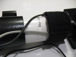
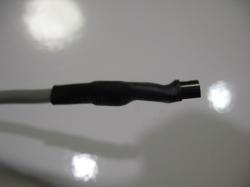
The dallas 1-wire temp sensors are run on individual channels although they are quite capable of being run in a chain. I find that works for me in terms of keeping track of which sensors go with which heater straps and for my usage 4 channels is plenty. I snip the leads short and connect to a light 2 core and shield cable. I use a 3.5mm stereo cable to plug those sensors into the controller.
The SHT10 sensor is housed inside the controller case with the sensor facing a hole driller in the side of the controller case. I’ve got my connections soldered to the breakout board because I’ve not managed to get decent connections to a socket which fits, others may do better with that. More recently I’ve used a two pieces of terminal socket strip cut to fit which is much neater. I’m going to try a piece of a two row version of this. For those seeking more channels the same concepts could be used based around an Arduino mega which has many more PWM channels than the Pro-mini. It could also be beneficial to put the microprocessor directly onto the board rather than buying an Arduino and connecting it. I was not confident that I was ready for that step but for the more experienced it could be simple. The PCB’s I had made included a few things I was not happy with, I had one track connected to the wrong place which I was able to work around, the 3 pin plug for the mode switch is too close to the other two 3 pin plugs and I’d have liked to have the power circuits done in a wider trace. I’ve updated the incorrect track and the position of the mode socket on a revised layout and amended the track thickness for the power circuits but have not had any built to the new layout so treat it with caution). Some additional labels on the board would be useful for assembly but I’m still learning how to do that stuff. Please treat the material as open source, use it, amend it, share it but don’t try to own it. See file link below to a zip containing the Eagle Schematic and Board Layout. I’ve not included any RF filtering in this, if those with a better understanding on how to achieve that are willing to provide input I’ll be more than pleased. I’ll be happy to try and answer any questions or take revisions from those with more experience.
 |
|