ICEINSPACE

|
Widefield EQ Suitcase
Submitted: Monday, 26th February 2007 by Tommy Boswell
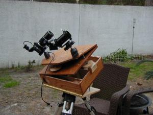
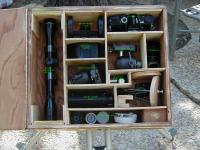
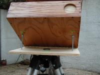
This design was modified from an idea by Robert Reeves in his book “Wide-Field Astrophotography, exposing the universe starting with a common camera”. Published by William-Bell, Inc. copyright 2000 The size of the over-all kit is dependant upon the equipment you need. First gather all the parts (equipment) and lay them out in some kind of order to find out approx. what size container you will require. Mine turned out to be 14 X 14 inches. Then I drew it out on the AutoCAD. I can e-mail these if you have the capability to read an AutoCAD drawing. If not, graph paper would work as well. Basically, the entire box is an EQ platform complete with an altitude adjustment (wedge) which can be eliminated if your tripod has the ability to adjust altitude on its own. The altitude adjustment is the shelf attached to the bottom of the box and is adjusted with bolts of a predetermined to length. These will match your latitude (more on that later). The lid of the box is hinged along the left hand side and needs to be parallel to the polar finder scope (I used a cheapo rifle scope), which is on the left also.
This hinge acts as the right hand ascension pivot and/or the polar axis. For your declination control another lid is affixed with hinges to the top of the lid, along the forward side (or the side facing the north or South Pole). Now you will have a box with two hinged tops which should be able to move in R.A. and DEC. plus an altitude adjustment (if needed).
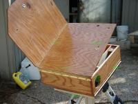
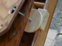
The control rods I used are ¼ x 20 carriage bolts with plywood circles for R.A. and DEC movement. I rounded out a depression where the bolt heads could pivot. Tee nuts were placed in the two upper boards. These must be inserted from the bottom and should be glued. I pulled them down really tight using a couple bolts and nuts and let the glue set several days.
My controls are 4 inch circles cut with a hole saw (the larger the better). On my first try the right ascension bolt was placed in the right hand corner so I could use both adjustment wheels easily but there was a lot of vibration so I moved it to the center. You must also cut a relief hole in the top board for the right Ascension screw to slide through so it doesn’t rub against or hit the top board. That solved the vibes but I had to make something for it to push against. That’s what the spare piece is here. A little planning can avoid this oversight.
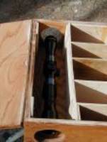
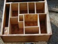
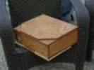
Also you should file down any imperfections on the head of the bolt to keep things moving smoothly. That’s the basic unit in a nutshell. However it was raining all weekend so…… I compartmented the interior to store all my equipment securely. If you decide to do this you need to figure the extra width of the wood used for compartments into your original sizing. Also a miscalculation on my part causes me to have to break the guide scope down completely (including the adjusting screws) so it will fit into the box. It’s too tall otherwise. The inside dividers were glued in using each successive one to brace the Last. No screws were needed.
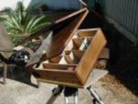
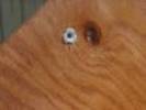
You’ll need to find the height needed to attain your particular lat. This could probably be done using a protractor but I did the math using the half length of the bottom of the box and the bottom support board. Remember the distance has to be measured from the pivot point NOT the end of the board!!! I double nutted two carriage bolts to the proper length, and on the support board I sank a rounded half hole with a round grinding bit for the bolt head to sit in. That keeps them in place. I drilled a ¼” hole over where the bolts would sit in the bottom of the box. To set altitude you just insert the threaded end of your two bolts into the drilled out holes and the head nests into the depression made in the support board. Your altitude is set exactly every time because the bolts are a fixed length.
To secure the whole thing I ran a bolt through and applied a wing nut. Hint: use one of your control bolts. Add a carry handle and your ready to start.
What you need: MATERIALS
EQUIPMENT
|
|
|||||||||||||||||||||||||||||||||||||||||||||||||||||