ICEINSPACE

|
Building a Pulse Width Modulated Dew Heater Controller
Submitted: Thursday, 16th March 2006 by Alan Sheehan
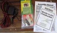
Parts Required
Tools Required
Pulse Width ModulationA Pulse Width Modulated Dew Heater Controller allows the temperature of the dew heater to be dialled up or down as necessary. Sometimes the dew is only light, so there’s no point heating the Optical Tube Assembly (OTA) more than necessary, and the controller provides this flexibility and while minimising power use from the power tank, or battery. Pulse width modulation is the way to go for a fully adjustable controller. The pulse width modulator turns the voltage on and off very quickly to the heater strip – about 2000 times a second actually. For less heat the voltage pulse spends more time off than on, and for high heat the pulse is on longer than it is off. This is much more efficient that using a potentiometer to reduce the voltage to the heater, since the pulse width modulator only draws as much power from the battery as is needed for the heater (in simple terms). There are several kits available for pulse width modulation controllers for various suppliers. The kits and parts list above are from Dick Smith Electronics, but the same or similar controller kits will be available from other suppliers as well. Which Kit do I need?
Deciding which kit to get probably comes down to the maximum current your heater will draw from 12V. The K3070 kit is limited to 1amp current maximum, the K3072 is good for something like 20amps if you need it! (The K3072 kit was first published as a project in Silicon Chip Magazine June 1997 edition). In my case, my heater measures at 11 ohms. From V = I x R, this means at 12 V the current, I = 1.1 A. So I need to use the K3072 kit anyway. Since this is the case, I thought “why not use the extra capacity and provide 3 outlet sockets when I build it? That way, if I need to, in the future, I can also run heaters for a guide-scope or piggy back lens, and perhaps even an eyepiece heater”. Building It
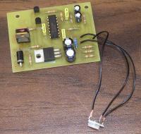
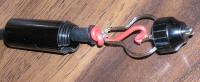
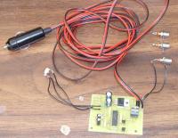
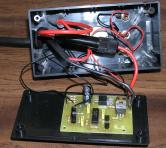
The instructions provided with the kit are clear and comprehensive, and a little guide book supplied with the kit covers all the basics of building electronic project kits. The K3072 kit is rated as a learner’s kit, and I presume the K3070 is the same. Follow the instructions when soldering the components to the printed circuit board (PCB). The kit comes supplied with a 5 kohm trim pot to adjust the pulse width. This just won’t do to adjust the heater once it is in a box, so I used hook-up wire to connect it to the PCB rather than solder it in place. This would do for testing until the pot I finally intended to use for this job arrived in the mail. When assembling the cigarette lighter plug for the power lead, remember that the plug is centre positive. Also remember to tie a knot on the cable inside the body of the plug so that the wires aren’t pulled off the soldered connections if the cable gets tripped over in the dark. If you are using the heavy duty power cable, you will find space a bit tight inside the plug body for this. I chose to get a good solid wrap of wire around the negative contact before soldering, and knotted the positive wire only before soldering to the centre pin – see figure 4. Figure 3 shows the guts of the controller assembled enough for testing. Again there are good instructions in the kit to step you through this. Since my controller would only be operating at low currents, I did not bother installing the supplied heatsinks on the MOSFETs. This is all laid out in the kit instructions. Note also that figure 3 shows the power cable in medium duty power cable – again so I could progress the project while waiting for parts to arrive. After passing the tests in the kit instructions, I hooked up the heater and gave it a test run as the final acid test. …mmm toasty warm…
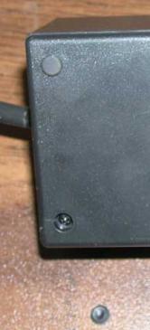
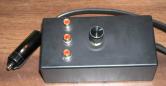
After testing, and it all works good, it’s time to fit it all into a box. The kit specifies a H2853 Zippy Box, which by the way is not included in the kit, so you need to buy it separately. The H2853 is discontinued (at least with Dick Smith’s anyway) so the right replacement box is a H5003. I chose to mount the PCB to the lid of the box, and the potentiometer and outlet RCA sockets through the “bottom” of the box, with the power lead in one end. PCB mounts can be used, but I had none handy so I used double sided (automotive) tape to hold the PCB to the lid. Again remember to knot the power lead on the inside of the box prior to soldering to the PCB. All the RCA sockets are wired in parallel i.e. all the centre contacts are connected to the positive output, and all the outer contacts are connected to the negative output pin on the PCB. I also chose to put the fuse holder (supplied with the kit) inside the box, to make it just that bit tidier once it is all assembled. It means it isn’t convenient to replace a fuse, but hey, it shouldn’t happen often unless you’ve got problems, and if that’s the case, you might want to be looking inside anyway to find the problem. The kit comes with a capacitor and a diode to wire across the terminals of electric motors, but these can be safely omitted when driving a resistive load like a dew heater. The kit also has a built in soft start feature which can be disabled by omitting capacitor C2, but I left it in – it won’t matter to a dew heater. Because my main OTA heater would be drawing 1.1A max, and I proposed to use up to 2 more heaters off this controller, each drawing considerably less than the main OTA heater, I reasoned that a 3A fuse should be fine for my needs. If I was just running the one heater, I would probably have chosen a 2A fuse. No doubt a 1A fuse would be appropriate to protect the K3070 kit. The box comes supplied with screws and rubber feet that fit into the counter-bored screw holes and make a neat job of finishing off the box – see figure 6. Figure 7 shows the completed Pulse Width Modulation Dew Heater Controller, with a knob on the potentiometer that I recycled from some other thing electronic. So for under $40 or $50, depending on your choice of cables and kits, you can build your own PWM Dew Heater Controller, and it’s not a bad way to spend a rainy afternoon.
AddendumAddendum to Dew heater Circuit using Silicon Chip PWM DC motor controller The Dew Heater circuit described uses a 12 Volt regulator. Three terminal Voltage regulators need around 2.5 Volts (Vin) above their rated output voltage (Vout) for them to operate correctly, colloquially called “headroom” voltage. The national data sheet refers for Vin/Vout specifications of 3 terminal regulators: http://www.datasheetcatalog.com/datasheets_pdf/7/8/1/2/7812.shtml If your circuit is powered from 12VDC then this regulator may interfere with the cct operation. Thus if you are powering your Dew heater controller from a 12 Volt source (regulated 12 Volts source) you should omit the Dew heater 12 Volt regulator and in lieu solder a wire link from the it’s Vin to Vout pads. These diagrams show the amended circuit:
 |
|
||||||||||||||||||||||||||||||||||||||||||||||||||||||||||||||||||||||||||||||||||||||||


![dew_heater_schematic_[800x600].jpg](content/images/cf518c89015e0580713b2af8f1f82001.jpg)
![heater_cct_board_copy_[800x600].jpg](content/images/7cbeeafad277ae679745ec1fbe888cc1.jpg)
