ICEINSPACE

|
Another DIY Parallelogram Binocular Mount
Submitted: Wednesday, 28th March 2007 by Dennis Simmons
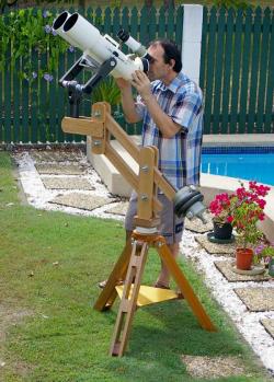
IntroductionAt the Queensland Astrofest in 2003 I stood mesmerised by the sight of a fellow astronomer, gliding effortlessly around the cosmos on his commercial, motorised, binocular chair, replete with GoTo capability. The whole two-eyed, recline-in-comfort, “drive-me-there” observing experience looked simply awesome. At the time, I had with me my Vixen giant binocular (30x125), supported by the very nice Vixen Alt-Az fork mount, all fitted on a home made wooden tripod. Using this set up I was able to view objects quite satisfactorily, even at the zenith (the binocular has 45° eyepieces), though scanning wider fields necessitated shuffling my observing chair around the tripod. This slow, jerky, crab-like, sideways waltz took the edge off an otherwise wonderful observing experience. Occasionally colliding with the tripod legs also proved a mild irritation! However, to offset this inconvenience, I was smug in the knowledge that motor-chair dude had only 25x100’s mounted on his whiz-bang GoTo chair! Some time later I looked at these motorised chairs on the internet, but their price range of $5000+ put them light years beyond my reach. Much later, I began thinking of a parallelogram design that incorporated the Vixen fork arms, to be used in a recliner. The main challenge would be the weight – the binocular comes in at 11kgs and the combined weight with forks and finder amounts to 16kgs. That is, 16kgs of glass and metal floating above your face!
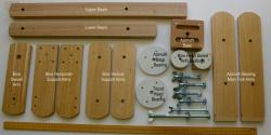
I started the design at the fork mount support end, working backwards to select components and materials that would support this substantial cantilevered weight. Fortuitously, some wood off-cuts from a neighbour’s home renovation provided me with some very nice timber that looked stout enough to do the job, so the project finally got underway. Always at the back of my mind, I had Plan B, which was to make the mount dual purpose, easily configurable for our much lighter 12x50 binocular, just in case the Vixen giants proved to be too unmanageable. Plan B also involved incorporating a 5th degree of motion capability at the binocular end, allowing me to sweep a slice of skies between 60° and 90° wide, simply by rotating my head up to 30° or 45° either side of centre. This was crucial as it would be wholly impractical to have to constantly reposition the reclining lounger, in order to sweep adjacent slices of the celestial sphere. DesignThe mount is made up of a number of main units; the Tripod, Parallelogram & Fork Arms Assembly and the Binocular Alt-Az Unit. This article will concentrate mainly on the Parallelogram & Fork Arms Assembly, which is made up from various sub-assemblies as described below:
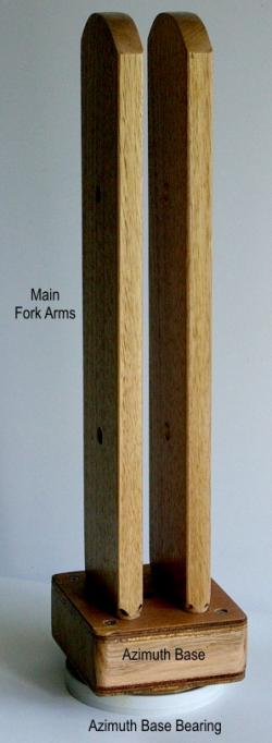
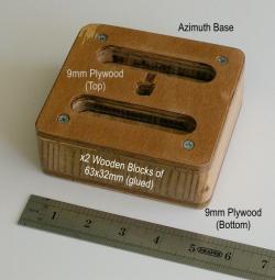
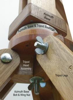
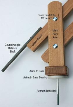
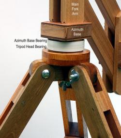
Azimuth Base & Main Fork AssemblyThis assembly fits onto the Tripod Azimuth Bearing and is made up of the Azimuth Base and Main Fork Arms. Refer to Figure 2 for details.
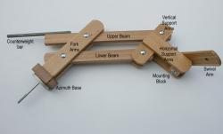
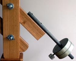
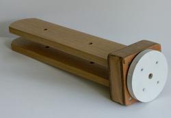
Parallelogram AssemblyThis comprises the (longer) Upper Beam and the (shorter) Lower Beam along with the counterweight balance arm. These form the parallelogram assembly with the Main Fork Arms at the tripod end and the Binocular Support Assembly at the viewer (binocular) end. Refer to Figure 3 for details.
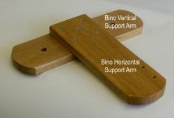
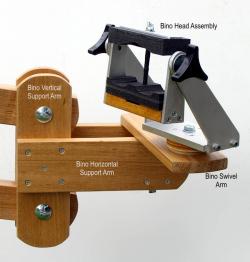
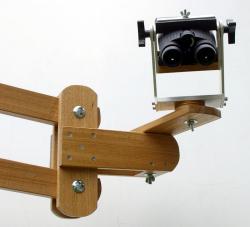
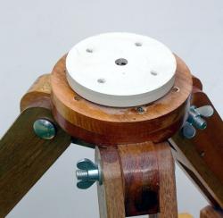
Binocular Support AssemblyThis assembly fits on the binocular end of the parallelogram assembly and consists of the Vertical & Horizontal Support Arms, (see Figure 4) and a Mounting Block (see Figure 5) for direct attachment of the Vixen 30x125’s Fork Arms, or the (smaller) Binocular Alt-Az Unit.
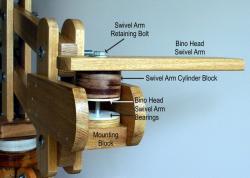
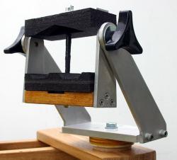
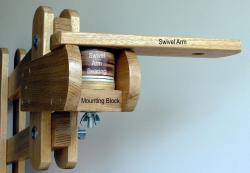
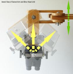
Binocular Support Swivel ArmThis piece of wood plus the cylindrical block of wood that fits in between the Horizontal Support Arms provides the all important 5th degree of motion allowing the viewer to sweep up to ¼ of the skies without the need to move the lounger or tripod. Binocular Alt-Az UnitThis small assembly is a simple, home made Alt-Az mount fabricated from aluminium and wood, fitted to the Swivel Arm (5th degree of motion) that pivots inside the Binocular Support Arms Assembly. It is only fitted and used for smaller binoculars, such as our 12x50’s. Refer to Figure 6 for details.
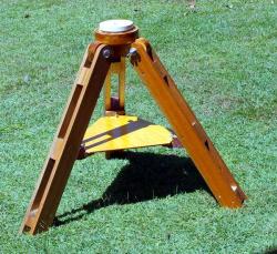
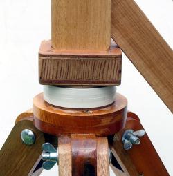
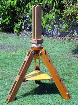
TripodThe tripod was a home made unit from a previous project. It was modified slightly to fit an Azimuth Bearing surface made from a PVC plumbing end cap. We will not describe the tripod design and build process in this article, restricting ourselves to the parallelogram mount assembly. Refer to Figure 7 for tripod details.
Materials and ConstructionI’ll provide the dimensions for the mount that I built, but these can be tailored to suit your particular requirements and set up. The embedded photos show the construction reasonably clearly, so I won’t add a step-by-step text description, although I will describe some important matters that will help with the construction. These are:
Azimuth Base & Main Fork Assembly
The 2 off 120 mm blocks of 63x32 mm hardwood were glued and clamped together and when the glue had set, the two top and bottom plates from 126x120x9 mm plywood were glued and screwed in place to strengthen the blocks. Two 19mm wide slots were routed out to accept the shaped bottom ends of the Main Fork Arms, which were glued in place. Long wood screws (3 inch) were then inserted from the under side of the base assembly, their action pulling the ends of the main forks into the routed out slots. These forks are going to have to support a lot of weight so this assembly has to be strong. Take great care in ensuring that the spacing between these main forks will accommodate the parallelogram beams, plus a few coats of varnish. Parallelogram Assembly
Binocular Support AssemblyThis assembly is illustrated in Figure 10 and consists of the following components.
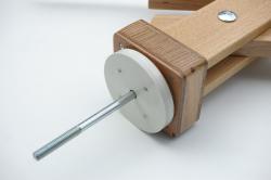
Binocular Alt-Az UnitThis was conceived as Plan B for our smaller 12x50 binocular, which do not have a ¼ inch tripod attachment socket. Refer to Figures 6 & 12 for details of construction. The upper and lower (shaped) black foam inserts hold the 12x50’s snugly. The centre post is a length of 6mm threaded rod that has been covered in black tape to avoid the metal threads from marking the binocular. A wing nut bearing down on an strip of aluminium bar (20mm wide x 3mm thick) allows the top foam unit to be pressed firmly down to hold the binocular in place once the correct Inter-Pupilary distance has been set. BearingsThe Azimuth Base Bearing, Tripod Bearing and the Binocular Head Swivel Arm Bearings were made from PVC plumbing caps in various sizes, fitted onto wooden blocks for stiffness. These provide a reasonably smooth motion, although very small adjustments can be a little sticky at times.
Bearing AxesThe main Azimuth Base Bearing Bolt is a ½ x 9 inch coach head bolt that passes through the Azimuth Base, Azimuth Bearing and Tripod Head as shown in Figure 13. Tension is controlled by a wing nut. The Parallelogram Beam Assembly is assembled using four off, ½ x 4 inch coach head bolts retained with washers and wing nuts. The Swivel Arm pivots around the axis of a 10mm x 130mm bolt with a wing nut allowing for fine adjustment of the tension. Refer to Figures 5 & 12 for details.
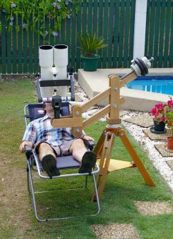
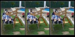
General NotesDegrees of MovementThis particular design has 5 degrees of movement. The first 4 are as follows: 1 – Azimuth movement at the main bearing where the mount joins the tripod. I added an “extra” 5th degree of movement to provide for sweeping extended segments of the skies without having to either move the lounger, or contort my neck. This extra, or “5th degree” of movement was provided by the swivel arm, which pivots on the binocular support arm. This allows the binoculars to be swivelled L-R across the front of the observers face, making it feasible to lie prone in a lounger, or remain seated on a chair, yet able to sweep approx ¼ of the heavens without having to move the mount, lounger or chair, but still feel relaxed and comfortable. All you need do is pivot your head around the neck – a natural movement, whilst pushing away, or pulling in, the Parallelogram arm. See Figures 15 & 26 for an illustration of this.
Range of MovementThe vertical range of movement of the parallelogram assembly is around 76 cms. Counterweights requiredFor the Vixen 30x125’s – 20kgs. Dual ConfigurationBy adding the Swivel Arm and Alt-Az Unit, the mount can be converted from supporting the Vixen 30x125 binocular, to carrying our 12x50s with the addition of the 5th degree of movement. This is a no-tool change over. Additional Construction PhotosHere are some additional photos that show general construction details and alternate views of some of the assemblies and components.
System Testing and Safety of Use IssuesThe design was not based on any quantitative engineering or mathematical calculations, relying simply on a gut feeling that the timber and fastenings employed would be more than adequate for the sheer weight of the Vixen giant binoculars. However, as the project progressed, I became keenly aware of the quite significant weights, moments and forces involved, so I decided to conduct a series of weight & balance tests before I put the unit into use. Here are the results: Fitted with a 12x50 binocularNo operational or safety issues were discovered in all orientations and possible configurations of the system. Fitted with Vixen 30x125 binocularSome operational and safety issues were noted with various configurations of the mount as follows:
It was interesting to note that when the assembly was fully loaded, with the parallelogram beams horizontal, by firmly tightening the 4 wing nuts, the parallelogram beam would remain horizontal when the Vixen giant binocular was removed from the mount, even with 20kgs of counterweight fitted. Vibrations induced by moving the binocular took approximately 5 to 6 seconds to dampen down to zero. Operational RestrictionsWith the Vixen giant binocular fitted, based on the above testing, I decided that the unit was okay to use by myself as I am aware of the operational and safety limitations, and also by my wife under supervision. It is probably not suited for use at astro camps, even by experienced astronomers and certainly not suitable for public viewing. General safety issues
ImprovementsArguably, the design is not really suited to these giant binoculars, but the existing unit could be improved by:
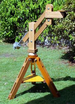
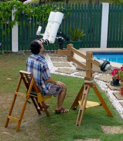
In the FieldHere are some photographs of the unit in use, in various configurations.
AddendumI have just discovered an excellent article describing “Binocular Mount Degrees of Movement” on the Cloudy Nights Binocular Forum. Article by Dennis Simmons (Dennis). Discuss this article on the IceInSpace Forum.  |
|
||||||||||||||||||||||||||||||||||||||||||||||||||||||||||||||||||||||||||||||||||||||||||||||||||||||||||||||||||||||||||||||||||||