ICEINSPACE

|
Classical Spectroscope
Submitted: Tuesday, 31st October 2006 by Ken Harrison
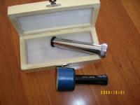
Christian Buil’s web pages are definitely the place to start (http://astrosurf.com/buil), he covers everything from the theory of spectroscopy through to examples of the calculations needs for the various lenses, spacing etc. BackgroundI started with a handheld spectroscope (GOTO). This direct vision spectroscope is used on stars (placed between the eyepiece and the eye), and contains three small prisms of different glass (flint and crown) producing a spectrum which is then “extended” into a short visible line by the use of a small cylindrical lens.
This basic instrument is powerful enough to show differences between planetary nebulae and stars; and different spectral classes of stars. (Wow, Oh Be A Fine Girl Kiss Me Right Now, Sweetheart!) Kaler's "Stars and their Spectra" book is an excellent reference on all aspects of astronomical spectroscopy. Currently handheld spectroscopes (with a built in slit) can be found at The Surplus Shed ( www.surplusshed.com) for about US$80. The next step up is to use either a prism or transmission grating to allow photography of the spectra of the sun and many other bright astronomical objects. A 60° prism placed in front of a camera lens will produce a spectra which can be recorded. This method can be used for star clusters, comets, and the occasional bright meteor. Similar results can be gained from a cheap replica grating (200 L/mm - lines per millimetre, or better) These are readily available from Educational supply shops, look for “Paton Hawksley” brand.
The next quantum leap (if you excuse the pun) is to use the additional light grasp of the telescope to image the light from the object either onto the prism (or grating) and connecting a camera to record the spectra. This allows fainter objects to be recorded. The commercial Rainbow Optics ( www.starspectroscope.com) spectroscope is a replica grating type which fits just inside the eyepiece and can show rotational period of Jupiter and Saturn as well as detailed stellar spectra. Combining a wedge prism (say, 5 deg angle) with a transmission grating can give spectacular results. This combination is called a “grism”. Bit of TheoryWhite Light is made up from a combination of light which has difference wavelengths. Wavelength is measured in nm (nanometre) (10 *–9 metre). (1/1,000,000 of a mm). The shorter the wavelength the bluer it appears, the longer the wavelength the redder it appears. Like telescopes, spectroscopes are measured by their resolution, that is, their ability to “separate” different wavelengths. Without going into the detail right now the resolution is directly related to:
Looking at gratingsThere are two main types: transmission and reflection, the transmission grating are usually made from plastic “replica’s” of a master grating and can cost from $5 upwards. The reflection gratings are made by scratching precision grooves or lines (rulings) on an aluminium coated glass sheet and can cost $150 upwards. The preferred option for the astronomers is the reflection type. (for reasons which will become obvious very soon). They come in various lines per millimetre (L/mm); from 150 to 2400 lines. The 2400 line has the potential to give very good resolution, but in doing so will also disperse the visible spectrum over a far longer image. This means that not all the spectrum will fit in the field of the camera and multiple exposures may be needed to capture the whole picture. With a 1200 L/mm grating and my MX7C CCD camera I need about 12 images to cover the solar spectrum. Putting it TogetherA Classical spectroscope is made up of five main elements:
How it WorksThe image of the sun, star, galaxy etc is focussed on the slit (using the telescope optics); the slit in turn is positioned at the focus of the collimating lens so that the beam of light which hits the grating is parallel; the grating disperses the light into a spectrum which in turn is focussed by the camera lens onto the eyepiece/ film/ CCD. That’s it in a nutshell. Why the slit?If you read any older book on spectroscopy you’ll probably find it spends half the words/ pages talking about slits and how difficult they are to make and adjust. Why are they so important?? A couple of reasons: ideally the light must be presented to the grating as a parallel pencil ideally aligned with the rulings on the grating and secondly the spectra image produced by the camera lens is a “picture” of the slit FOR EACH WAVELENGTH. I.e. if there were no slit, just a small round opening, then the spectrum seem would be a collage of small coloured disks overlapping along the image… making it very difficult to see the fine detail. Generally the finer the slit gap, the better the detail.
The width of the slit can vary from 2 to 50 micron wide ( 2/1000 to 50/1000 of a mm), depending on the object and the available light. The good news is that The Surplus Shed also sell great, adjustable slits for $ 20. No need to get involved in the mechanical issues of making one. (Believe me I’ve done it; just buy one!!) If you really must try to make one; start with the blades pulled from a disposable razor, use blu tac or similar to hold them in place and adjust them against a bright light with a toothpick to give a uniform small gap.
The CollimatorThis is generally an old binocular objective, or a surplus achromatic lens. There are two important aspects to consider for the collimator.
The GratingIMPORTANT: Never touch the front surface of the grating; it is extremely difficult to clean (some say impossible!), keep them in an enclosed container when not in use. Dust is the second worse enemy. Handle with extreme care at all times. Generally reflection gratings of interest to amateurs come in two sizes, 30 x 30mm and 50 x 50mm. Prices do vary, but the ones from Optometrics (http://optometrics.com/prod/spectro/gratings/gratingbrochure.pdf) are US$120 for the 30 x 30mm and of good quality. I’d recommend starting with a 600 or 1200 line grating. It’s also possible to get gratings where the grooves are cut with such a shape to concentrate the reflected light into a preferential direction (this is called “blazing”) This is well worthwhile paying for as it allows fainter objects to be recorded. Buy the largest grating your budget will allow, this is the “heart” of the spectroscope.
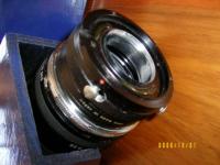
When designing the optical layout of the spectroscope you will need to define the angle at which the grating will be set to the collimator and the camera lens. Generally the angle between the collimator and the camera lenses will be about 37 degrees. Buil’s excellent spreadsheet should be used to verify the angles and lens sizes (see appendix). The design of the spectroscope should allow the grating to be positioned as close to the collimator as possible, and the grating should be mounted to allow rotation of at least 20 deg. Ideally the centre of rotation should be through the centre of the grating and aligned with the front surface of the grating. In the Lhires design of Buil, he uses a micrometer to adjust the position of the grating; by reading the micrometer it’s possible to measure the wavelength of the various lines in the spectrum. I’ve used a small stepper motor drive for the same purpose. The grating must be held firmly in the holder at right angles to the optical axis of the collimator and camera lens. The lines on the grating run vertically up down. Camera LensAgain must be large enough to “catch” all the light from the grating i.e. similar size to the collimator. Most amateurs use old camera lenses of 135 to 200mm focal length. I use a Tamron 135 f2.8 lens. This lens, as mentioned earlier, is set about 37 deg to the collimator and aligned on the optical axis. By using standard T ring adaptors it’s easy to interface with film cameras, Webcams, and DSLR’s. This lens is set fully open (f2.8) and focussed at infinity. CCD chip (or eyepiece/ film)The pixel and overall size of the CCD chip are important. The smaller the pixel the better the resolution and the larger the chip the more of the spectrum recorded. In Buil’s spreadsheet he provides the calculation details for various chip sizes. An eyepiece can also be attached behind the camera lens for visual use. A 25mm/ 40mm Plossl gives good “Oooh Ahhh” results. If the spectroscope is being used on stars, just bear in mind the typical exposures (for a mag 5 star) are in the order of 6 x 5min = 30 min total. The solar spectrum only needs 1/20 to 1 sec exposure.
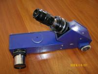
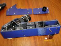
Construction NotesWeight is an issue. A typical spectroscope can weigh (with CCD camera) up to 4 Kg. This means counterweights and re-balancing of telescopes and drives. Also remember you need to be able to keep the image of the star on the slit for minutes at a time. If you use a transmission grating the camera lens is then a long way from the telescope and gives major headaches with vibration and balance. (Hence the universal preferred use of the reflection gratings.) Steve Dearden (http://astrosurf/dearden) gives some very good notes on general construction. Construction materials can vary from 4mm aluminium sheet, Perspex, through to custom wood chipboard. As long as the optics can be held rigidly in place with minimal flexing, anything goes. I used 6mm ply for rigidity and ease of working. The final overall weight came in at 1.9Kg. I went for a 60mm x 60mm box arrangement, overall sizes to suit the lenses I had to hand.
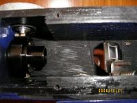
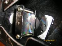
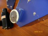
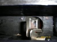
The slit mechanism is held in a piece of 18mm custom wood, which allows some fine adjustment. A small grub screw locks it in place. The adjustment knob doesn’t protrude very much, so I ended up adding an extension to both seal the area and give finer control. The exterior disk could be calibrated to give precise settings of the slit gap. (See notes later) The 40mm binocular lens (collimator) is mounted centrally in a 6mm divider. I’ve fitted an old 100 tooth gear I had to the shaft and can use this manually to set the angle of the grating. A small stepper motor with a smaller matching gear (about 3:1 ratio) allows for semi-automatic adjustment from the computer.
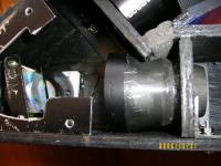
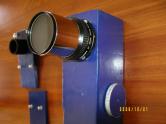
To get the camera lens as close to the grating as possible (135mm f2.8 lens) I used an old filter to make an adaptor to screw into the front of the lens, this adaptor is glued with epoxy and mounted in a 6mm divider. I sealed the gap between the edge of the divider and the main box with foam to keep dust out. This construction easily allows the use of other camera lenses and provides a rigid coupling to the spectroscope.
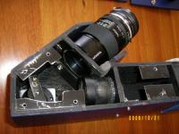
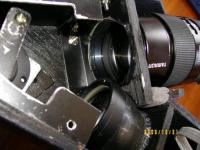
Double check the alignment of the slit and collimator; this must be as accurate as you can make it. I drilled a 30mm hole in the box behind the grating to allow the use of a finder telescope to check the focus of the collimator on the slit. After “dry” fitting all the components to make sure everything went together, I glued the dividers in place. (Later I added additional aluminium angle for added support; not sure they were necessary but I felt more comfortable!) Matt black interior and your choice of external paint. The lid is in two parts (only because I messed up the positioning of the beam splitter and had to extend the main box!!) This obviously gives access to the slit, grating and lenses. Again I added aluminium angle for additional rigidity. By setting the grating to the zero position you’ll get an image of the slit in the camera, this allows for fine tuning of the slit position and slit gaps, and gives confirmation that everything is aligned and working. DustThe biggest problem in real life (other than finding a star!) is dust. ANY dust on the edges of the slit WILL show up in the image. This gives rise to longitude lines in the spectrum “transversalium”. Keeping the slit clean is mandatory. Remember cleaning the grating is almost impossible, so this should be protected at all times. Likewise any dust on the collimator and camera lenses will affect performance. Try and seal the spectroscope as completely as possible. Setting the slit gapOne of the most elegant solutions I’ve seen is to use a laser pointer. As the light goes through a very narrow slit, interference patterns are produced. These can be projected onto a suitable wall and the distances between the bright fringes measured, there is a direct co-relation between these measures and the actual slit gap. See http://astrosurf/thizy/lhires3/e_reglages.html for details. Guiding and Beam splitters/ flip mirrorsYou’ll quickly find it’s a challenge to get a star focussed on the slit and hold it there during a series of 5 minute exposure!!!! Buil in his Lhires model adds a small “telescope” to view the image of the star on the edge of the slit. I elected to introduce a beam splitter in front of the slit to allow setting and guiding. You could use a flip mirror to set up the spectroscope on the star but you lose the ability to guide. This item gave me the most headaches. There must be an easier way! Unfortunately the beam splitter needs about 165mm of focal distance to get the image to the slit and push it out the spectroscope to allow auto guiding (either with a Webcam or in my case an old ST4 CCD). The support frame of the beam splitter came from another project and necessitated enlarging the box to fit it in. Adjustment is via the side panel.
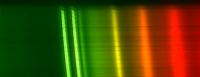
TestingThe obvious candidate for testing your new spectroscope is the Sun. It’s easy to get a usable spectrum without even mounting the spectroscope in a telescope. Just point it so that the Sun shines directly on the slit (even a bright sky can give results). The slit should be reasonably open i.e. a visible gap. By turning the grating you should quickly find the 1st order spectrum. Magnificent view!! CAUTION To be honest, I’m not game to focus the sun through my 12” LX200 onto the slit of the spectroscope. I’m sure something would cook. The “best” I’ve done is to stop the aperture down to 50mm and then focus on the slit. No ill affects, but certainly much more light than is required to give a good image on the CCD. The Fraunhofner lines (dark lines caused by the elements in the sun’s atmosphere) should be visible. There are a couple of easy targets; three lines in the green (Magnesium) and two in the yellow (Sodium). If the slit is aligned with the grating and the camera lens is focussed on the eyepiece/ CCD these lines should be clearly visible. If not, try rotating the slit slightly, it may also help to narrow the slit gap slightly.
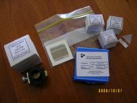
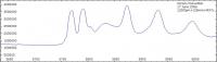
Reference Light SourcesTo really appreciate what the spectroscope can do- like measuring the rotation period of Saturn, distinguishing the composition of various stars, looking at the gas and dust in comets and recording the rise and fall of supernovae etc. We need to be able to record the spectra and compare it with others to determine the elements involved. A reference source of a known light which shows measurable bands/ lines is necessary. A neon light bulb (Jaycar have a small bulb, needs to run at 70V – achieved by putting a suitable resistor in a 240V circuit) is well documented. Some of the energy saving fluoro bulbs have been mapped. I’m using a Philips Genie bulb, which gives good emission and absorption lines as a reference.
Measuring SpectraAfter recording the spectra say on CCD (convention says the blue part is always to the LHS) any standard photo-editing package can be used to stitch the sections together. Valerie Desnoux has developed a freeware program “Vspec” (http://astrosurf.com/vdesnoux) which allows calibration and measurement of spectra. It provides compensation for the colour sensitivity response of the CCD, and normalises the spectrum based on similar reference stars. Initially difficult to learn, but well worth the effort. There’s also a series of tutorials and support forum to help newbies. Article by Ken Harrison (Merlin66). Discuss this article on the IceInSpace Forum. Appendix
 |
|
||||||||||||||||||||||||||||||||||||||||||||||||||||||||||||||||||||||||||||