ICEINSPACE

|
Making Your Own Artificial Star
Submitted: Friday, 13th January 2006 by Barry Waters
Having set aside some prime viewing time to accurately collimate my small Mak, I grew repeatedly frustrated that I seemed to be using good observing conditions to sort out the scope and just as I started to make some headway, over came the clouds. During some correspondence with another user of my scope via the Yahoo groups on the subject of collimation, I learned of such a thing as an artificial star. Intrigued, I queried the existence of such an aid during a visit to Bintel in Sydney, whereupon I was shown the very one they use to check and adjust collimation on all their scopes prior to sale. Now, I class myself as a fairly capable DIY’er with some common sense and simply won’t part with the hard earned for items as easy to build such as this, particularly while there are other more worthy potential purchases to be made. Coupled with the fact that I had some spare time with not much to do I talked myself into making my own. The result is a tool which can be used prior to collimate your scope at any time. Shopping list
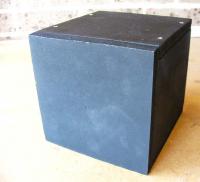
All up, assuming you already have the MDF or shipboard plus adhesive and screws, the total project cost could be as little as $10.00. The biggest cost would be the cable if you construct your star using a manufactured lead which will set you back around $22.00 alone. The star consists of one end of a fibre optic cable fitted into the centre of a darkened plate, (the viewing plate) a small led light source and a battery to provide power.
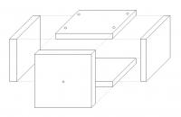
The size of the front plate should be large enough so that when you are focusing on the “star” you only see the black plate in your FOV. This size could be determined by placing the telescope viewing a wall at a distance from which you intend to collimate from. Using some help, direct an aid to place two vertical chalk marks on the wall at your FOV extent, add say 10mm and this would be your final size of square viewing plate. Of course some of you experts will be able to calculate it I daresay. Using some sturdy material for the box such as 10mm or larger chipboard or MDF (mine is 16mm), cut out three squares to the dimensions you determined from the wall marking activity. These will be the front, top and bottom of the cube. Two further pieces should be cut but rectangular, one dimension equaling the dimension of the three pieces already cut and the other to be the same dimension less twice the material thickness you are using. These will become the side walls.
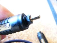
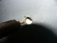
Obviously, the squarer you cut, the neater the finished star will look. The sides do need to be square and flat in order for the glue to bond well so take some time here and uses a good circular saw for minimal planning later. Pick one of the three square plates and draw two diagonal lines from each corner to find centre. This is where we will drill the hole which the end of the optical fibre cable will locate within. I found that PVA adhesive is all that is needed for fixing the front, bottom and two side walls together. I used quick release clamps to hold the pieces while I adhered them one at a time and in the 30C heat this took approximately 15 minutes before I could handle them again. There will be some variability for the next step. I was unable to purchase a single strand of fibre optic cable but had a spare manufactured lead for some dvd signal transmittal purpose so I doctored this lead to fit. This entailed cutting the thin plastic wall away from the socket part of the termination to leave just the terminated core of the cable exposed.
I measured the diameter of the now exposed copper sheath around the actual optical cable (accurately using vernier calipers) and drilled a hole of the same dimension in the front plate to give a tightish push fit. The rear of the plate was bored out to a larger diameter to accept the plastic termination plug as I needed to push the fibre optic through from the rear of the plate until it was flush with the front surface. You won’t need to do this obviously if you are using un-shrouded cable. The final plate is the top plate which I screwed onto the top of the two side walls as this may need to be removed at some stage for maintenance should anything go wrong. Drill holes to take four suitable sized screws as shown in previous pics. Once the adhesive is dried and the box can be handled easily, spray the whole thing with the chalk board paint. It isn’t necessary to spray on the inside although I did as it looks a bit more professional and I had no other use for the paint.
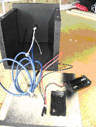
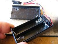
The battery container was fixed to the underside of the top plate by gluing the lid to the wood using the PVA adhesive. The battery holding compartment is simply slid into place and locates so it stays together. Be sure to pick a spot close to the open ended rear of the unit though to make changing of batteries easier. The pos and neg leads are then soldered to the led wires for electrical connection although small “chocolate box connectors could be used if this is easier for you. To reduce the risk of shorting, I insulated the leads of the lead prior to connecting and wrapped each exposed joint with insulating tape. Remember that the longer lead on the supplied LED is positive and should therefore be connected to the red wire of the supplied battery box. The shorter to the black wire.
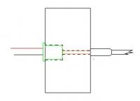
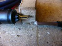
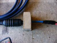
Coupler block LED light is very directional in that it needs to be viewed head on in order to benefit from its brightness. Therefore we need to mount the LED firmly and show it to the fibre optic cable in an aligned manner. I did this by using a small piece of waste material from the box manufacture. A 3mm hole was drilled just deep enough for the LED to be pushed in nice and square and tight. From the same end I drilled a smaller hole to accept the cable using the bottom of the first hole as a guide and drilled right through the coupler block. The blocks thickness was devised so as to allow the fibre optic cable to practically touch the LED in order to trap all available light. See the sketch below. The thickness of the block was equal to the length of the led from the bottom shoulder plus the length of the shrouded cable.
It is wise to connect all the components and test that you actually have light transmitted to the end of the fibre optic cable via the coupler block at this point as we will be gluing the coupler block to the underside of the lid next. Select a position away from the open end but allow for nice easy coiling of the fibre optic so don’t allow it to foul up against the inside of the front cover and using PVA adhesive, glue into place. When all dry you are ready to connect up the internals and get collimating.. Daytime style! Just some notes. If ,like me, you have taken to using only nickel metal hydride rechargeable batteries (cos they’re the only ones which last any anount of time in today’s digital equipment), be aware that fitting these will dim the LED somewhat. Alkaline batteries give 1.5V when new, whereas Rechargeable NiMH give only 1.2V when fully charged. This 0.6V loss is considerable given the 3,2V rating of the LED and so you will lose somewhere close to 20% brilliance in your “star”.
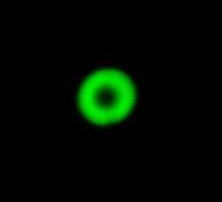
Overall, I feel the light given via the fibre optic cables is still somewhat big but it is very easy to see if collimation is out and to determine how to adjust the scope to bring it back. I easily and comfortably adjusted my scope set up next to a workbench with all tools laid out and, more importantly, a clean working area to place the eyepieces, screws and mirror housing each time it was removed. The whole job was so much easier. If required, a larger LED could be fitted with more batteries to power it if more light is desired and I guess this may be the case for those of you who want to collimate around 600X magnification. It’s a case of suck it and see but the new LED and battery holder will only set you back a few bucks. Article by Barry Waters (Muddy Diver). Discuss this article at the IceInSpace Forums.  |
|
|||||||||||||||||||||||||||||||||||||||||||||||||||||||||||||||||||