ICEINSPACE

|
ST80 Finder on a 12" Dob - An Experience
Submitted: Monday, 13th July 2009 by George Vasilareas
1. IntroductionMy telescopes include 6”, 10” and 12” GSO Dobsonians, three refractors, one SCT and one PST. I observe from my backyard and from a semi dark site, some fourty five kilometres away. I store one of my Dobsonian in a shed at the dark site. The 10” and 12” Dobsonians have been fitted with Argo-Navis encoders. I store them fully assembled and moved them, quite easily and very quickly, by a common and inexpensive trolley. I suffer from astigmatism and I need to wear eyeglasses all the time. The standard 8x50 or 9x50 GSO and similar finders are optically good. However their eyepiece have a plastic lip protruding the eyepiece lenses and my eyeglasses were getting scratched when I tried to see the full field of view in the finder. Since I wrote this, I trimmed this plastic lip and I placed a piece of black felt with adhesive backing around the lenses of the eyepiece, so scratching of my eyeglasses is not longer a problem. Between 2004 and now, significant industrial development and increased light pollution took place about one kilometre from my backyard. As a result of this, I’ve lost at least one magnitude at zenith. I now estimate the limiting magnitude at zenith to be 3.5 to 3.8 at best. The combination of these reasons made me decide to upgrade the size of the finders on the Dobs. An Orion ED80 and a 120ST were considered for both the 10” and 12” Dobs, however they were quickly rejected because they were too long and heavy. Instead a ST80 was selected for its low weight, short length, short focal length and low cost. The notes and the photographs shown below describe my experience in installing this ST80 finder. I hope that my experience could be of some help to others considering a ST80 or similarly sized finders. 2. First Experience - ST80 Finder on a 10" DobPhotos Ph.1 to Ph.8 below, show my first attempt of erecting an ST80 finder on the 10” Dob. The balancing system for this finder was put together without much thinking and this caused some problems when viewing. The ST80 finder is fixed by a pair of 135mm inside diameter guidescope rings to an aluminium rail. The aluminium rail is composed of two open sections, a “U” section without lips and another section with lips. The two sections are riveted to each other. The composite section is bolted to the tube by ¼” bolts, nuts, washers and spring washers. The combination of the composite rail and the rings is very stiff. The shape of the composite rail is also very convenient for quickly adjusting the position of the rings without any tools. The combination of rail and the rings set the longitudinal axis of the ST80 finder about 135mm away from the tube.
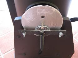
The balancing system consists of three counterweights and a friction brake. Two of the counterweights are 1 kg ankle weights fixed by Velcro and a tensioned strap. The third counterweight is 1.2 kg dumbbell weight and it is secured to the tube by the same tensioned strap used for the ankle weights. The friction brake consists of a 3mm thick, aluminium circular plate. It is fixed to the altitude plastic bearing by the same bolts the bearings is fixed to the tube. This aluminium disk is pressed against the side boards by means of a furniture slider fixed to a steel bar. The bar is fixed to base boards by two winged nuts and spring washers. The amount of pressure and friction may be easily varied from zero to completely locking the tube in altitude.
The ST80 with a 1.25” diagonal and a 22 mm Panoptic, gives a TFOV of about 3.6 degrees and the star images are very good.. The ST80 also acts as a RFT. I was very satisfied and happy with the ST80, both as a finder and as RFT. But I was not very happy with the tube balance and fluidity of motion in altitude. The reason for that was, that I did not consider the mechanics associated with the system, although I could have done so by ease as I have the necessary expertise. Photos Ph.7 and Ph. 8 below show why and the notes explain that.
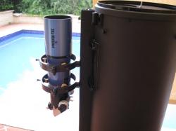
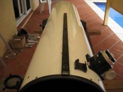
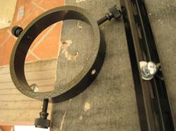
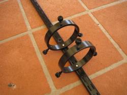
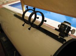
Refer Ph.7. The tube is pointing high in altitude. Notice that both the position of the ST80 and the counterweight are to the left side of the centre of the altitude bearing, i.e. the pivot point in altitude. The ankle weights are just below the pivot point. The centre of gravity of the ST80 is just above its focuser. This centre of gravity is to the left of the point of rotation of the tube in altitude. The rotation produced by the ST80 in this position is anticlockwise. The counterweight at the bottom of the tube is also located to the left of the point of rotation of the tube. It produces an anticlockwise rotation as the ST80 does. So this position of the counterweight makes things worse. The ankle weights (not seen in this photo, as they are behind the side board) are just about below the point of rotation and their net contribution is just about zero. So, with the tube pointing at high altitudes, most of the counterbalancing contribution must come from the friction brake. The friction brake worked as it was supposed to do. It stabilised the tube against rotation in this position, but in doing so, the tube movement in altitude became very stiff. This was a major distraction to viewing which had to be remedied. See Ph.8. The tube is pointing at about 45 degrees in altitude. The position of the ST80 is to the right of the centre of the altitude bearing and all counterweights are to the left of it. This centre of gravity is to the right of the point of rotation of the tube. The rotation produced by the ST80 in this position is clockwise. Now observe the counterweight at the bottom of the tube. It is located to the left of the point of rotation of the tube and it produces an anticlockwise rotation, that is opposite to that of the ST80. In other words, it opposes the rotation produced by the ST80. The ankle weights are also to the left of the point of rotation producing an anticlockwise rotation as the counterweights do. So in this position both the counterweights and the ankle weights oppose the ST80 rotation. For this reason, very little contribution is required from the friction brake for low altitude pointing. The tube movement in altitude was not affected much by the friction brake and the movement of the tube was quite fluid and satisfactory. The experience of having a scope with very stiff altitude movement made me think of a different approach to balancing the ST80 on the new 12” Dob and on the older 10” Dob. This had to be done without the friction brake. The new approach is described below, followed by a detailed but simplified explanation of the mechanics associated with balancing heavy finders. 3. ST80 Finder on a 12" DobThe new rail has a lower profile that the composite rail used in the 10” Dob and described above. It is a standard, two slot shelving rail, which is commonly fixed to walls to support short horizontal brackets, which are cantilevered from it. These cantilevered brackets support shelving boards. The finder rings used, are Orion Guidescope rings with an internal diameter of 105mm. The rings and the rail now place the ST80 tube closer to the Dob’s tube. The fixing of the rail and rings is shown and described on the photographs below.
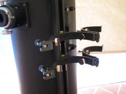
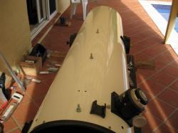
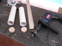
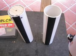
I choose to fix both the rail and finder rings in a way that they can be removed without disturbing their supports. In the case of the rail, the bolts are fixed onto the Dob tube and have a short section protruding above the nut. The holes in the rail allow it to sit on the tube and be fixed in position by nyloc nuts. Removing or replacing the rail will not interfere with the bolt heads inside the tube. In the case of fixing the rings to the rail, the same principle was adopted. Two bolts were fixed to the rail, with a short section of the bolt protruding and having enough length to finish flash with the inside of the ring. The rings were then treaded into protruding section of the bolt. The material for the balancing weight system were selected on the their availability and cost. I had some of these materials left over from some construction work. They consisted of PVC pipes, wood, concrete reinforcing steel bars, steel treaded rod, Velcro and straps with tensioners. The trolley, with a rated load of 250Kg, was bought from a local hardware store for less than the cost of two 200mm diameter pneumatic tyres. The 60mm diameter PVC pipe, which holds the counterweights, was checked for clearance behind the tube and the front or side base boards. This arrangement is shown in the photographs below.
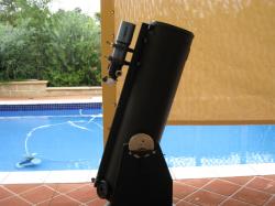
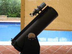
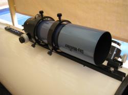
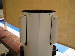
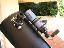
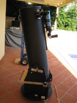
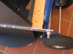
During this work, the 12” Dob tube was painted flat black. The photographs below show the completed system of ST80, its support rings and its counterweights in place. They also show excellent balance at different altitudes with the ST80 finder, a TV Paracorr, a 35mm Panoptic.
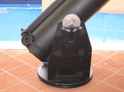
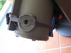
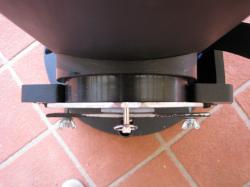
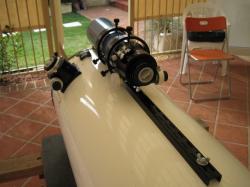
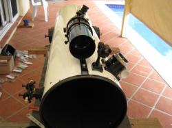
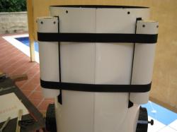
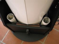
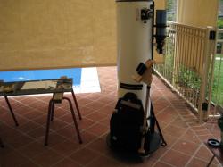
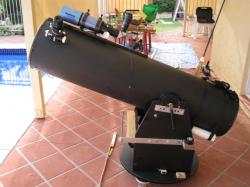
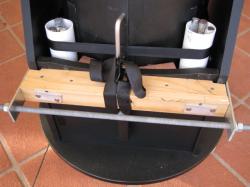
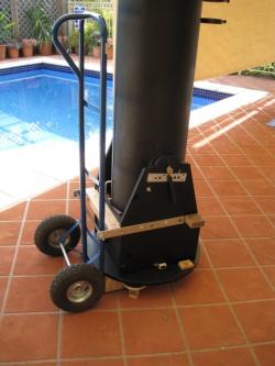
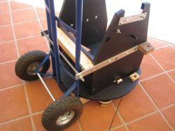
Refer Ph.25: Tube pointing at high altitude. Very good balance with no slip. Note that the horizontal steel flat bars fixed to the side board, the piece of timber fixed to the front board and the 12mm treaded rod have nothing to do with the balancing system. They are used to move the assembled scope with the trolley shown in the background. Refer Ph.26: View of the lower part of the mount. There is a total of 16-16mm diameter – 200mm long reinforcing bars in both the PVC tubes to balance the ST80 and the heavy Paracorr and 35mm Panoptic. The tension in the springs provides some additional resistance to tube rotation. When a lightweight eyepiece is in the focuser some of the bars are removed to again provide excellent balance. Note that the lower cupboard handle has been fixed to the tube in order to attach the strap and fix the tube to the base during moving. There are two small timber wedges fixed to the front base board. Their position makes the tube vertical to the base when aligning for the A-N setup. Refer Ph.27: This photo shown the way the scope is moved about, stored and taken up ramps. It consists of a common trolley found in most hardware stores with 200mm diameter, pneumatic tyres. The trolley is secured to the scope by means of two steel flat bars and a treaded rod with nuts washers, spring washers and nuts at either ends. The rod is treaded through the holes of the flat bars and in between the trolleys vertical tubes. The nuts are tightened by thump and figure pressure. The strap (see Ph.26) secures the tube in position. During moving, the tube, base and trolley behave as one unit. The finders stay aligned. The ArgoNavis encoders are always in position. When the telescope is not in use, it is wheeled into a room. Setting up and storing the scope is very quick. I consider it as a grab and go in relation to set up time, excluding of course the cooling and alignment of the optics. Refer Ph.29: Closer view of Ph.28. This shows that the trolley arms is in contact touch the packing timber piece which is fixed to the front scope board. It is also in contact with the circular base board.
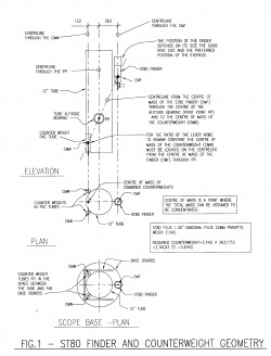
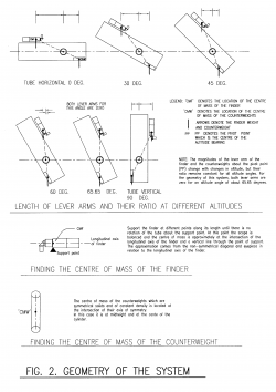
4. Balancing the Weight of the ST80Good counter balance of the extra weight of the ST80 finder was the most important part of the project. For Dobsonians, the resistant to movement in azimuth is provided by the friction between the base board and the Teflon pads. I have found that the size of the Teflon pads that come with the scope to be inadequate and I replace them by new 50mm by 50mm ones. I also place a Teflon pad under the central bolt. The resistance to movement in altitude, is provided by friction between the plastic altitude bearings and the Teflon pads fixed to the vertical base boards. The forces on the altitude bearings pads consist of two parts. The first involves the self weight of the tube, finders, eyepieces and anything fixed thereto. The second part is the tension in the altitude provided by the springs. Obviously for scopes without springs, things will be different. There is another very well known, but easily resolved balancing issue. It is associated with balancing the telescope tube in altitude for heavier eyepieces, including Paracorrs. In my experience this was a bit of a problem even before I decided to use the ST80 as a finder. I easily solved this by placing a 1.2 kg counter weight near the bottom of the tube. In determining the value of the required counterweight, it will be more accurate to consider all the weights or loads above and below the pivot point of the altitude bearing and them calculate the exact value of counterweight, assuming that size and position of the eyepiece is constant. This can be easily done, when the geometry of the centres of mass and the masses are known or established. This is a three dimensional problem but it is easily solved. In working out of the size of the counterweight, I made the simplifying, but reasonably accurate assumption, that everything is balanced except the combination of my heaviest eyepiece, a 35mm Panoptic and the Paracorr. This made the problem a very simple, two dimensional one. My previous experience indicated that I needed about 1.2 kilogram of counterweight for this. The ST80 finder plus a 1.25” diagonal plus a 22mm Panoptic weigh 2.1 Kg. The total counterweight is that required for the ST80 plus one kilogram for the 35mm Panoptic plus the Paracorr. The position of the ST80 finder on the tube, will depend on the size of the rings and on its comfortable location of the eyepiece. The location of the centre of mass of the ST80 plus diagonal plus eyepiece can be easily determined. A simple way to establish this, is shown in Fig. 2 below. The type, size and shape of the counterweights may vary, but they must clear the baseboards and the likes, they must be compact, their length in relation to the telescope tube must be short and they should be preferably made from a material with high unit weight. Once the particulars of the counterweights are decided, its centre of mass can be located as shown on Fig.2 for simple geometries. The location of the centre of mass of the counterweights is fixed, by a straight line drawn from the centre of mass of the ST80 finder, through the pivot point of the altitude bearings and extended to the opposite side of the tube. This description is shown on the annotated sketches shown on Fig. 1, below. This must be strictly observed in order to keep the ratio of the lever arm of the ST80 and the counterweight constant at all altitudes. In this case the ratio of the lever arms is 1.72. This means that the counterweight for the ST80 must have a mass of 1.72 times 2.1Kg, i.e. 3.6Kg, plus the additional one kilogram mass for the 35mm Panoptic and Paracorr. The maximum value of the counterweight is about 4.6Kg.
The extra mass on the tube from the ST80, diagonal, eyepiece and counterweight is about 6.7 Kg. This is about thirty four percent of the mass of the tube, the tube being about 20Kg. This extra weight has the beneficial effect of increasing the friction at the altitude bearings also by thirty four percent as well. 5. General RemarksBoth the 10” and 12” GSO Dobs have now ST80 finders. One is stored in a shed on a “semi” dark site and the other in a storeroom with direct access to my backyard. Red dot and laser finders are also attached to each Dob. Both ST80’s have finder brackets on them and 30mm or 50mm finders may also be attached. Argo Navis encoders are also permanently erected on both Dobs. Taking the Dobs out of the storeroom and setting them up involves wheeling them to the required spot, remove one nut which secures the treaded rod to the scope and trolley and move the trolley out of the way. Packing up involves putting the trolley against the scope’s base, tread the rod in position, place and tighten nut, and wheel scope to its storing place. It takes very little time indeed to set up, pack up and store. I find this very convenient and I do not have to think twice about taking the scope out. It takes me the same time to set up my grab and go scopes which have the tubes permanently mounted. So overall I am very happy with this setup. Even if I decided to use a 50mm finder, I will keep the scopes permanently setup. In reality, I could get away without using the ST80 finder and the associated counterweights because the ArgoNavis is very accurate and in my experience, it always puts the object in the field of view of a long or medium focal length eyepiece; but the ST80 acts as a rich field telescope at the same time. I also find the ST80 very useful to find objects without the use of Argo Navis. The setup described above will not be time efficient if I had to removed the telescope tube and all attachments from its base, put in car and drive to another site. I haven’t tried this but I have the feeling that it will be a bit inconvenient. The altitude encoder would have to be removed, the ST80 taken out from its ring, the counterweights removed, the tube placed carefully in the car so as not to damage the finder rings, repeat the procedure in reverse order at the observing site and then disassemble and pack the car again. If I had a van, it will be a different story. Moving just the tube with the ST80 and counterweights attached will be also difficult due to its size and weight. There could be some future problems with this setup. Two come to mind. The first is some damage or wear of the plastic altitude bearing due to extra weight. The second is some damage to the tube in the areas where the bolts secure the bearing to the tube. However, the scope being a Dob enables one to fix problem like these, very easily. Article by George Vasilareas (astrolabe). Discuss this article on the IceInSpace Forum.  |
|
||||||||||||||||||||||||||||||||||||||||||||||||||||||||||||||||||||||||||||||||||||||||||||||||||||||||||||||||||||||||||||||||||||||||||||||||||||||||||||||||||||||||||