ICEINSPACE

|
Power Drive and Equatorial Platform for a Dob
Submitted: Wednesday, 10th October 2007 by Dennis Greeve
It all began with the purchase of a Toucam digital imager and processing the AVI images in Registax. Working with Mike Salway’s suggestion of traversing the image across and parallel to the Laptop Computer screen, which, if my interpretation is correct, overcomes the declination aspect, was only half the answer. Recording Jupiter and using what I call the return method of processing, described some months earlier in IIS, I could capture and stack 180 frames, but with moon recordings the number of frames are markedly reduced if one wishes to obtain a reasonable size balanced picture of interest. Twenty frames minimum to fifty maximum with luck, was the best obtained. If one could stop the Azimuth movement, assuming Mike’s method as described above took care of the declination, for a period of 30 to 40 seconds, I would be able to capture the full selected image of the moon with 300 to 400 frames. I first made a hand operated control, which failed miserably, causing excessive telescope shake. It had to be motorised.
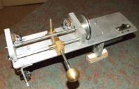
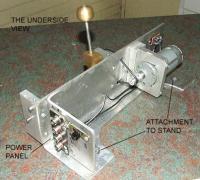
The method used is not new and has been used by numerous Dob enthusiasts to drive their platforms, the difference being the method I chose to build it. I settled on 20 TPI - ¼ inch Whitworth drive shaft –, which I hoped the chosen DC geared motor would drive at a speed of approximately one revolution in 30 to 40 seconds. A friend who had used a YG2738 12v DC geared head motor for a model train turntable suggested using it for its high torque and low RPM. The motor has lived up to his recommendation and was first made with a direct connection to the threaded drive shaft. While building the pulse system controller, a star test was made using a simple voltage reduction, 100ohm pot and a 2.5 ohm 5 watt resistor, the motor voltage was reduce to bring the shaft RPM down to one revolution in 15 seconds, which proved to be too fast. Moving the motor to the underside of the base plate and fitting pulleys and an O Ring belt drive gave a further 3:1 reduction.
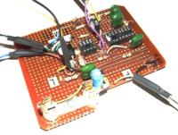
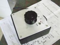
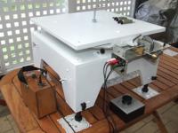
The electronic Motor Speed Pulse System Controller can be found on the Web. PWM DC Motor Speed Control, by G. Forrest Cook. The 0.05 uf capacitor on pin 2 and 6 of the NE556 oscillator, requires changing to 0.0056, otherwise the circuit is built as shown. Just remember to electrically isolate the heat sink for the Power Fet. I used IRF 540N. The Fet shown in the original circuit is an old listing and was not available. The lid to the Perspex plastic box made for the controller is 3mm aluminium and provides the heat sink. A switch and red LED is provided, which I feel is a must when working in the dark. Pic 3 shows the completed circuit without the two ICs, made on Vero Board - A circuit diagram is not provided on the Web.
The cables providing 12 volt power, from a small rechargeable lead acid battery and to and from the hand held control box, are colour coded RCA connectors - old stereo sound cables - The Illuminated Finder Scope and Laser Finder - both described in previous IceInSpace articles, and the cooling fan are all powered from the same source with suitable voltage regulation.
Bench tests proved most satisfying. The drive shaft rotated at one revolution in 85 seconds at the slowest speed. Pulse systems create noise, but it reminds one that the drive is on, which is a plus under dark conditions. Although the simple arranged drive would stop the Right Ascension, it did not stop the Declination and to achieve what I had hoped for it was obvious that an equatorial platform was the only way to go. I chose the Warren Peters design, which would accommodate the existing drive unit without any modifications. It is well presented and appeared to be easy to make.
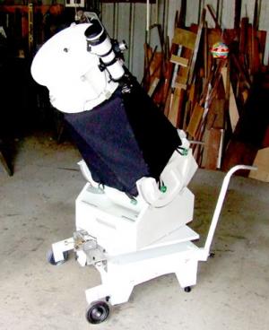
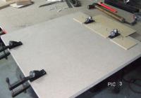
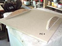
The Dob scope is weighty and beyond my years to lift on and off the proposed platform, so a new movable base had to be designed and the equatorial platform would be an integral part of it. The top board of the platform is a free unit, just sitting on the four bearings and held from moving sideways by the drive pin, which, if disengaged from the threaded drive shaft is free to move either way. It became obvious that the top board carrying the weighty scope needed locking down when the whole assembly was being transported within my house yard and four locking down bolts and spacers that lift the telescope weight off the platform bearings are screwed down at the four corners when required. Also four levelling legs sliding in square steel tubes for total rigidity are fitted to each corner of the base unit, allow the platform to be levelled.
The existing wheelbarrow design was modified with new handles, all removable. The assembled scope has proved easier to move and with the aid of a simple lever and a twin cross level it can be levelled in a few minutes. The most rewarding part was the success of the first test. The Toucam, a 2x Barlow and the laptop all set up, I had Jupiter on the screen and turned the drive on at the slowest setting The image moved slowly right to left across the screen. Increasing the drive speed the image slowly moved left to right. A small adjustment to the controller and the image stopped central to the computer screen. I captured 219 frames before stopping the capture. For the first time I was able to use all without ticking the required number of frames in Registax and such a pleasure to focus a stationary object.
I doubt Warren Peters will read this on IceInSpace, but I thank him for publishing his ideas and in conclusion consider this: The platform is 480mm square and carries the full weight of the heavy scope and yet it moves so little for 40 seconds of capture. The drive shaft turns approximately twice in 40 seconds. The pitch is 20 tpi, which is close to 1 mm per revolution, representing a total movement of 2mm, (approx) which shows the need for accuracy in manufacture of the two curved runners.
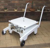
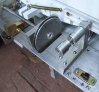
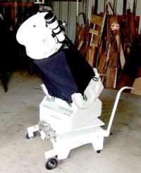
Rotating the scope to capture the image puts a lot of strain on the half nut and drive shaft. To overcome this I have fitted a spring loaded platform lock that locks the top board of the platform from moving, while allowing the scope to be rotated. When ready to capture, the plunger is released leaving the platform free to move. I feel this modification is very important. It prevents the half nut being stripped and brings the platform back central each time. The picture on the left below shows this addition. The last picture is the completed platform and scope.
 |
|
|||||||||||||||||||||||||||||||||||||||||||||||||||||||