|
Bendy Scope Light
Submitted: Thursday, 4th May 2006 Michael Samerski
The following design is something I use to illuminate my gear that I lay out between the tripod legs. The gear is my eyepiece set, laptop, battery box and other assorted stuff. I like the idea of a bendy light as it allows you to point it anywhere easily. I haven't been able to find a commercial one, especially with a red light, so I decided to make my own. Total cost was about $15 (AUD). Construction time was 90min. The Ultra Bright LED can deliver an enormous amount of light. Enough to illuminate a large area around your equipment. You will find that it is enough light to enable you to setup your entire rig in pitch dark.
I power my scope with a 7.2Ah 12V sealed lead acid battery. The current drawn by an Ultra bright LED is very small compared to driving the scope. A quick test showed that I could easily run the light at full brightness for days.
 |
 |
|
Click to Enlarge
Bendy Scope Light
|
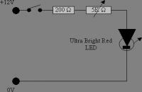
Circuite circuit below shows the components required to build the bendy scope light.
The 200Ohm resistor sets the maximum current that can be draw and thus the maximum brightness. The voltage across the LED is effectively a constant 3.6V so decreasing this resistor value too much will cause the LED to draw enough current to destroy itself. The potentiometer serves as a dimmer, limiting the current that the LED can draw. Increase the value of the 5K potentiometer to decrease the minimum light level. It's a good idea to not allow the minimum to fall below what is easily visible as you might find that you inadvertently leave the light on and flatten your battery. Bendy BitThe bendy bit is made from solid-core mains cable that has been stripped of its insulation. It is designed to be bent around on leg of the tripod or any other suitable object.
|
 |
|
Click to Enlarge
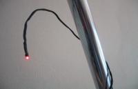
Bendy Bit
|
ConstructionTake two strands of the copper wire and twist the together to form the structure. Cut one length about ¼ shorter than the other such that the “tip” holding the LED only has one core and therefore is lighter than the main length.
Next solder the LED to its conducive wires and twist them around the copper core wires. Thread the entire set of wire through the heat-shrink. This is somewhat tricky and will take some time and patience. Leave some heat-shrink over the base of the LED to provide some support for the LED. Heat the heat-shrink to set it off being careful not to over heat the LED and damaging it.
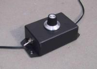
Control BoxThe Control Box has the function of power switch and dimmer. It contains all the required electronic components.
When mounting the switch, it's a good idea to ensure that the off position is down or oriented such that if it is accidentally thrown by something falling on it or getting knocked, it turns the light off. This will minimise the chance of accidental flattening of your battery.
|
 |
|
Click to Enlarge
Control Box
|
Components
- Bendy bit
- 1m 3.0mm Shrink Wrap
- 1m solid core 1mm wire
- 1m thin insulated wire
- 3.6V ultra bright LED (RED)
- 200 Ohm Resistor
- 5K Variable Resistor (Potentiometer) + knob
- SPST Switch
- Component box (“Jiffy box”)
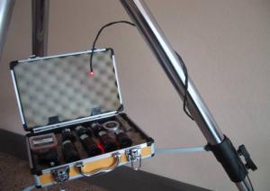
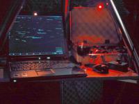
ToolsSoldering Iron, Side Cutters, Heater for shrink wrap (Gas stove), screw driverActionThis picture is of the light in action. Here you can see the eyepiece case and laptop mounted between the tripod legs. The light can be used to illuminate the laptop however my laptop (Thinkpad R50) has a built in orange light. The control box can be seen on the far right next to the laptop mouse.
|
 |
|
Click to Enlarge
In Action
|
Article by Michael Samerski (smersh). Discuss this article on the IceInSpace Forums.
|